
Flight time sensing system and ranging method thereof

A sensing system and time-of-flight technology, applied in the sensing field, can solve problems such as error in the detection results of TOF sensors, and achieve the effect of improving accuracy

Active Publication Date: 2019-11-15
炬佑智能科技(苏州)有限公司
View PDF5 Cites 11 Cited by
  • Summary
  • Abstract
  • Description
  • Claims
  • Application Information

AI Technical Summary

Problems solved by technology

[0004] However, in the prior art, especially when the detection environment is relatively complex, the detection results of the TOF sensor will produce large errors

Method used


Image

  • Flight time sensing system and ranging method thereof
  • Flight time sensing system and ranging method thereof
  • Flight time sensing system and ranging method thereof

Examples


Embodiment Construction

[0031] As mentioned in the background art, the time-of-flight sensor in the prior art has relatively large detection errors in a relatively complex detection environment.

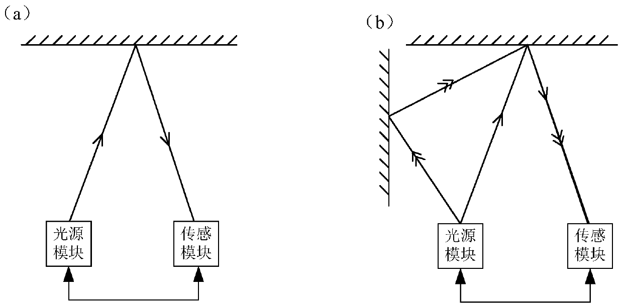
[0032] The inventors have found that part of the detection error is caused by multiple reflections. The multiple reflections are transmitted through multiple reflection paths with a long optical path and are received with a delay, which is the reason for the inaccurate detection results. The details are as follows:

[0033] Please refer to figure 1 (a), in this case, there is only one reflected light, the detection light emitted by the light source module directly reaches the surface of the object to be detected, and when the reflected light reflected by the object to be measured is directly received by the photosensitive module, according to the emitted light wave and the received light wave The time difference or phase difference between them corresponds to the distance.

[0034] However, in the actual ...


PUM


Abstract

The invention relates to a flight time sensing system and a ranging method thereof. The flight time ranging method comprises steps of: delaying detection light pulse frame by frame according to sequences of multiple detection frames; receiving reflection light after the detection light pulse is reflected by a to-be-tested object, and acquiring a plurality of initial depth values corresponding to the detection frames respectively; and selecting one of the plurality of initial depth values as an actually measured depth value of an output frame corresponding to the multiple detection frames according to a distance coefficient corresponding to the initial depth value, wherein the actually measured depth value is less than an initial depth value corresponding to a first detection frame, and theinitial depth value and the distance coefficient are in positive correlation. Through adoption of the flight time sensing system, interference of reflection light of multiple times can be weakened, and distance detection is more accurate.

Description

technical field [0001] The invention relates to the field of sensing technology, in particular to a time-of-flight sensing system and a distance measuring method thereof. Background technique [0002] The Time Of Flight (TOF) method realizes the measurement of the three-dimensional structure or three-dimensional profile of the measured object by measuring the time interval of the pulse signal sent by the measuring instrument from transmission to reception or the phase difference generated by the laser going back and forth to the measured object once. . TOF measuring instruments can obtain grayscale images and distance images at the same time, and are widely used in many fields such as somatosensory control, behavior analysis, monitoring, automatic driving, artificial intelligence, machine vision, and automatic 3D modeling. [0003] Time-of-flight (TOF) sensors generally include: a light source module and a photosensitive module; the light source module is used to emit pulse...

Claims


Application Information

Patent Timeline
IPC IPC(8): G01S17/08G01S7/486
CPCG01S17/08G01S7/4865
Inventor 黄勇亮梅健
Owner 炬佑智能科技(苏州)有限公司
Learn More