Working condition variable water spraying cooling device for high-temperature fuel gas

A technology of water spray cooling and water inlet device, which is applied in the direction of spray device, spray device, household refrigeration device, etc., can solve the problems of slow cooling response, complicated device structure design, equipment burning loss, etc., to reduce the loss of gas heat, Save test costs and enhance the effect of control performance

Inactive Publication Date: 2019-11-15
中国航发贵阳发动机设计研究所
View PDF7 Cites 3 Cited by
  • Summary
  • Abstract
  • Description
  • Claims
  • Application Information

AI Technical Summary

Problems solved by technology

In the traditional fixed nozzle or nozzle design, the size of the nozzle is mainly designed for the maximum working condition of the test piece. In the state of low gas temperature or small flow, in order to ensure the inlet heat flow temperature requirements of the exhaust pipeline heat exchange device, The water volume of cooling water can only be reduced through pressure control and adjustment. However, this will not ensure that the sprayed cooling water is always in the design condition. Generate local high temperature, resulting in equipment burning
The multi-stage water spray device (three or even more), although it can improve the cooling condition to a certain extent when the range of gas working conditions is large, but the structure design of the device is complicated, and the processing is extremely difficult, so it needs to be equipped with multi-stage spray Water pipelines and auxiliary adjustment equipment greatly increase the construction cost and the difficulty of test operation

Method used


Image

  • Working condition variable water spraying cooling device for high-temperature fuel gas
  • Working condition variable water spraying cooling device for high-temperature fuel gas
  • Working condition variable water spraying cooling device for high-temperature fuel gas

Examples


Embodiment Construction

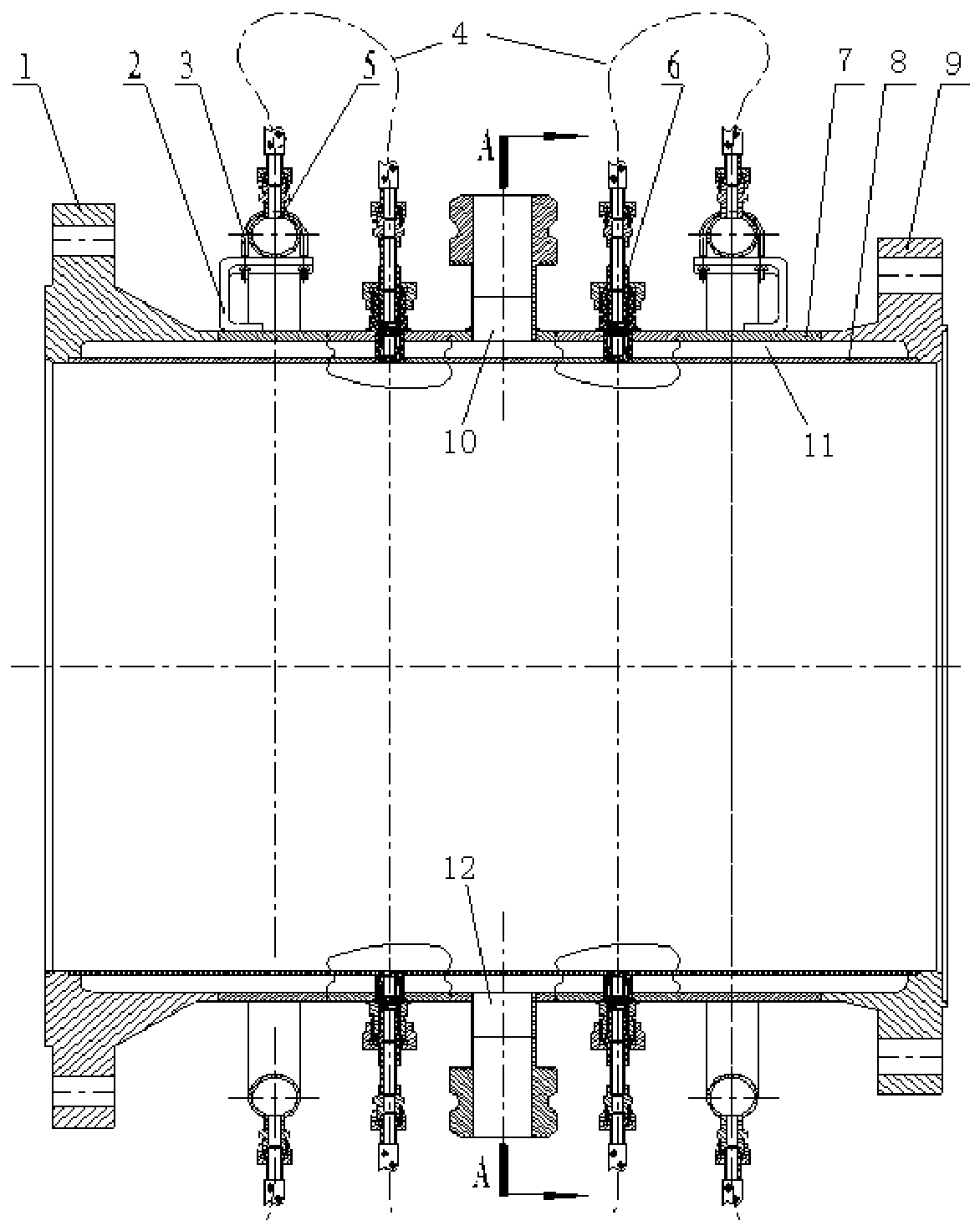
[0021] The present invention will be further introduced below in conjunction with the accompanying drawings. A variable-condition water spray cooling device for high-temperature gas according to the present invention includes an inner cylinder 7, an outer cylinder 8, a pipeline inlet flange 1, Pipeline outlet flange 9, several replaceable nozzle structures 6, several high-pressure water inlet devices 5, the inner cylinder 7 and the outer cylinder 8 are circular pipes (square and fan-shaped can also be designed according to needs), the pipes The inner ring of the pipeline inlet flange 1 and the pipeline outlet flange 9 is a groove structure, and the end faces of the grooves with large and small diameters are respectively welded with the inner cylinder 7 and the outer cylinder 8 to form an annular cavity 11. The bottom and top of the annular cavity 11 are respectively provided with a water jacket water inlet pipe 12 and a water jacket outlet pipe 10 connected thereto. It fills t...


PUM


Abstract

The invention discloses a working condition variable water spraying cooling device for high-temperature fuel gas; the water spraying cooling device comprises an inner cylinder body, an outer cylinderbody, a pipeline inlet flange, a pipeline outlet flange, replaceable nozzle structures, and high-pressure water inlet devices, wherein the pipeline inlet flange and the pipeline outlet flange are connected with the inner cylinder body and the outer cylinder body, so as to form an annular cavity; a water jacket water inlet pipe and a water jacket water outlet pipe which are communicated with the annular cavity are arranged at the bottom and the top of the annular cavity respectively; the replaceable nozzle structures are uniformly distributed on the wall surface of the outer cylinder body, anda nozzle mounting base at the bottom penetrates through the annular cavity and is connected with the outer wall of the inner cylinder body; the high-pressure water inlet devices are uniformly arrangedon the wall surface of the outer cylinder body, and the high-pressure water inlet devices and the replaceable nozzle structures are connected in a one-to-one correspondence mode. According to the water spraying cooling device, the defects of the traditional fuel gas cooling device are overcome, and the problem that the cooling water spraying is not easy to adjust under different gas working conditions is solved.

Description

technical field [0001] The invention relates to the field of high-temperature gas cooling, in particular to a variable-condition water spray cooling device for high-temperature gas. Background technique [0002] In the test of the main combustion chamber and afterburner of the aero-engine, a large amount of high-temperature gas will be produced (the gas temperature at the outlet of the afterburner can even be as high as 2000°C). In order to meet the temperature requirements of the exhaust pipe and the exhaust heat exchange device, it is necessary to The gas at the outlet of the combustion chamber is cooled and cooled, and the water spray cooling device is the most efficient for cooling the gas. However, due to the different flight conditions of the aircraft, the gas flow and temperature at the outlet of the combustion chamber vary widely. The gas flow may range from a few hundred grams per second to tens of kilograms per second, and the temperature will vary in the range of ...

Claims


Application Information

Patent Timeline
Patent Type & Authority Applications(China)
IPC IPC(8): G01M15/02F25D31/00B05B1/04
CPCB05B1/04F25D31/00G01M15/02
Inventor 杨珂龙霆汪洋唐阳
Owner 中国航发贵阳发动机设计研究所
Why Eureka
Try Eureka