
Fuel atomizing nozzle adopting single-electrode plasma jet flow and control method of fuel atomizing nozzle

A plasma and fuel atomization technology, applied in combustion methods, combustion chambers, combustion equipment, etc., can solve the problems of loss of activity, low reliability, poor atomization enhancement, etc., to improve reaction activity, reduce production costs, Improve the effect of distribution

Active Publication Date: 2019-11-15
SHENYANG AEROSPACE UNIVERSITY
View PDF6 Cites 6 Cited by
  • Summary
  • Abstract
  • Description
  • Claims
  • Application Information

AI Technical Summary

Problems solved by technology

[0005] The structure of the existing gas turbine plasma enhanced atomizing nozzle is relatively complex, generally consisting of a nozzle body, a dielectric layer, an inner electrode, an outer electrode, and an insulating layer
When working, the high-voltage end of the power supply is connected to the inner electrode, and the liquid fuel flows between the dielectric layer and the outer electrode to realize dielectric barrier discharge. The liquid fuel is ionized and atomized through the nozzle. However, due to the characteristics of dielectric barrier discharge, the discharge distance is relatively small. Small, it is difficult to achieve wide range and large flow of liquid fuel ionization, the ionization effect is relatively poor, and the positive and negative active particles are generated due to the ionization of the liquid fuel, and when the liquid fuel flows through the metal nozzle, some of them will collide with the metal wall and lose Active, strengthening effect becomes worse
[0006] Therefore, in order to solve the above-mentioned problems such as the narrow flow range of the plasma enhanced nozzle using dielectric barrier discharge technology, poor enhanced atomization effect, high injection pressure, and low reliability, the present invention provides a fuel oil nozzle using single-electrode plasma jet technology. Atomizing nozzle and its control method, which can realize the function of improving the atomization of liquid

Method used


Image

  • Fuel atomizing nozzle adopting single-electrode plasma jet flow and control method of fuel atomizing nozzle
  • Fuel atomizing nozzle adopting single-electrode plasma jet flow and control method of fuel atomizing nozzle
  • Fuel atomizing nozzle adopting single-electrode plasma jet flow and control method of fuel atomizing nozzle

Examples


Embodiment Construction

[0035] In order to understand the above-mentioned purpose, features and advantages of the present invention more clearly, the present invention will be further described in detail below in conjunction with the accompanying drawings and specific embodiments.

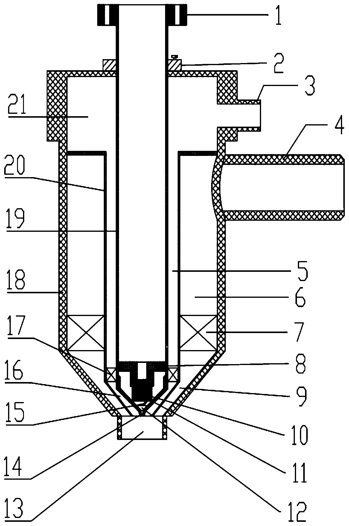
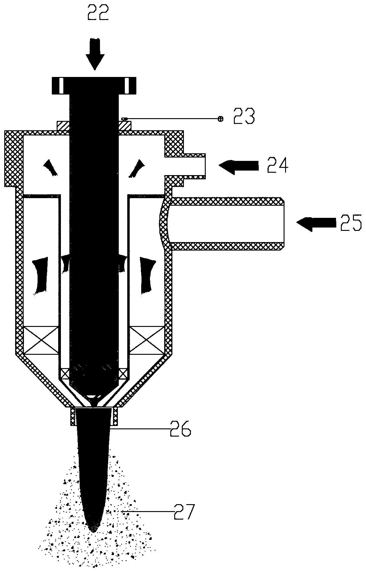
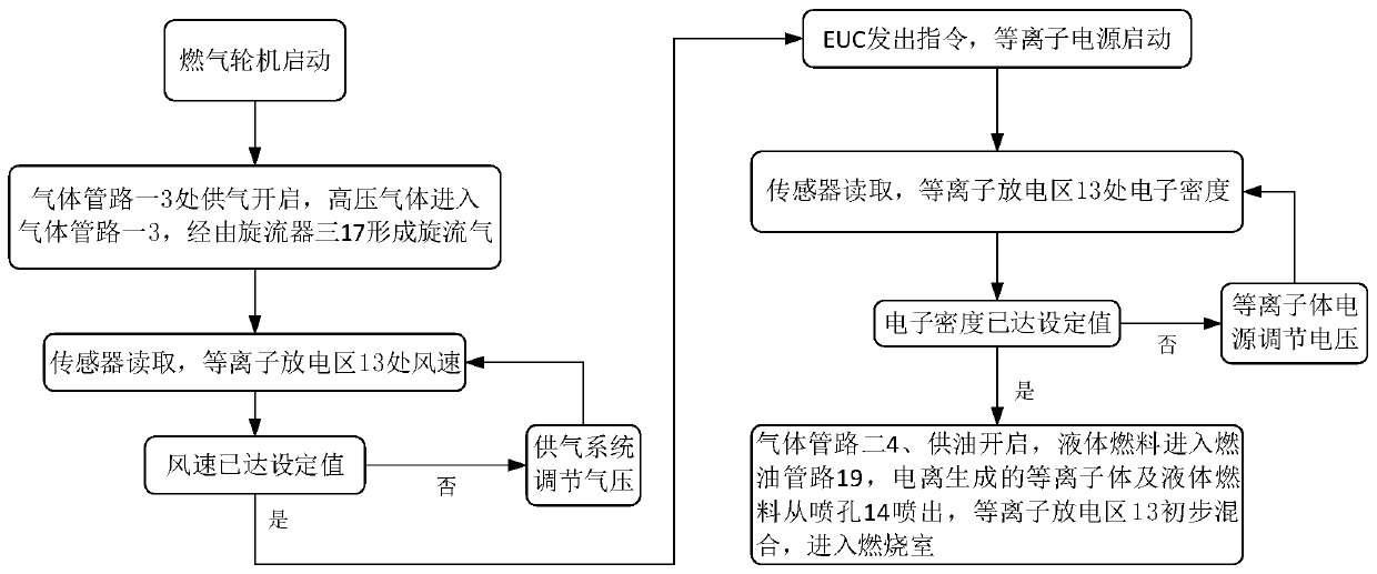
[0036] Refer below Figure 1-3 A fuel atomization nozzle using a single-electrode plasma jet and a control method provided according to an embodiment of the present invention will be described.

[0037] Such as figure 1 As shown, the present invention includes an injector, an insulating flange 1, an insulating housing 18, a high-voltage electrode connector 2, a fuel pipeline 19, a cyclone one 7, a cyclone chamber one 9, a cyclone three 17, a cyclone Room 3 16, gas pipeline, plasma discharge area 13, cavity, wherein the injector includes: oil filter positioner 8, oil filter 10, cyclone 2 15, cyclone chamber 2 12, nozzle hole 14, conical The contraction pipeline 11, the components of the injector are made of metal materia...


PUM


Abstract

The invention discloses a fuel atomizing nozzle adopting single-electrode plasma jet flow and a control method of the fuel atomizing nozzle. The fuel atomizing nozzle comprises an ejector, an insulating flange, an insulating shell, a high-voltage electrode wire connector, a fuel pipeline, a first swirler, a first swirler chamber, a third swirler, a third cyclone chamber, a gas pipeline, a plasma discharge region and a cavity, wherein the ejector comprises a filter positioner, an oil filter, a second swirler, a second rotational flow chamber, a nozzle and a conical shrinkage pipeline, the ejector can realize the introduction of liquid fuel and fuel injection and serves as a high-voltage electrode, so that plasma single-electrode jet discharge is realized, the distribution range of fuel atomization is improved by utilizing the unbalanced plasma pneumatic effect, the reaction activity of oil mist is improved by utilizing the unbalanced plasma chemical effect, and finally, the purposes ofimproving atomization, improving combustion, reducing emission level of harmful combustion products and reducing the ignition range are achieved.

Description

technical field [0001] The invention relates to the technical field of gas turbine fuel nozzles, in particular to a fuel atomization nozzle using a single-electrode plasma jet and a control method. Background technique [0002] Gas turbines are widely used in electric power, aviation, petrochemical and other industries due to their small size and large output power. The increasingly stringent energy conservation and environmental protection requirements have become the biggest challenge in the field of gas turbine research. With the continuous innovation of gas turbine technology, the combustion chamber is required to have characteristics such as reliable ignition, high combustion efficiency, and low pollution emissions under different loads and different working conditions. Therefore, it is urgent to develop clean combustion technology for gas turbines. [0003] Studies on combustion have shown that the atomization quality of fuel nozzles directly affects the combustion p...

Claims


Application Information

Patent Timeline
Patent Type & Authority Applications(China)
IPC IPC(8): F23R3/02F23R3/12F23R3/38
CPCF23R3/02F23R3/12F23R3/38F23R2900/00008
Inventor 陈雷杨聪曾文李政楷马洪安王美琪刘凯刘宇
Owner SHENYANG AEROSPACE UNIVERSITY
Learn More