
Oil-based drilling waste supercritical treatment system

A treatment system, oil-based drilling technology, applied in the direction of mining wastewater treatment, sludge treatment, special treatment targets, etc., can solve the problems of mud aging, unfriendly environment, inevitable secondary pollution of air pollutants, etc., to achieve low viscosity , the effect of high diffusion coefficient

Active Publication Date: 2019-11-15
HEFEI GENERAL MACHINERY RES INST +1
View PDF7 Cites 4 Cited by
  • Summary
  • Abstract
  • Description
  • Claims
  • Application Information

AI Technical Summary

Problems solved by technology

[0011] The newly configured drilling mud will have more and more impurities as it is used for a long time, which will cause physical changes, which will cause the "aging" of the mud. The "aging" mud will be processed by solid control equipment, such as dryer + centrifuge A certain degree of regeneration can be obtained after treatment by a machine, etc., but the separated waste and the mud with a deep aging degree still contain a certain amount of oil, generally still greater than 10%, some even reach 20%, and generally contain a certain amount However, such substances are not friendly to the environment. According to the requirements of environmental protection laws and regulations, oil-based waste cannot be discharged directly and needs to be treated. Usually, the treatment methods for such "aging" oil-based mud and waste include thermal analysis. , incineration, chemical cleaning, etc., but these methods have technical defects to a certain extent, for example, basically they will inevitably produce secondary pollution, and they are relatively sensitive air pollutants, and the processed products still exist. environmental incompatible components etc.

Method used


Image

  • Oil-based drilling waste supercritical treatment system
  • Oil-based drilling waste supercritical treatment system
  • Oil-based drilling waste supercritical treatment system

Examples


Embodiment Construction

[0075] Below in conjunction with embodiment technical solution of the present invention is made more specific description:

[0076] see figure 1 , this embodiment is composed of an extraction unit, a separation unit, an extraction agent recovery unit, an extraction agent filling unit, an energy recovery balance unit, and a control unit.

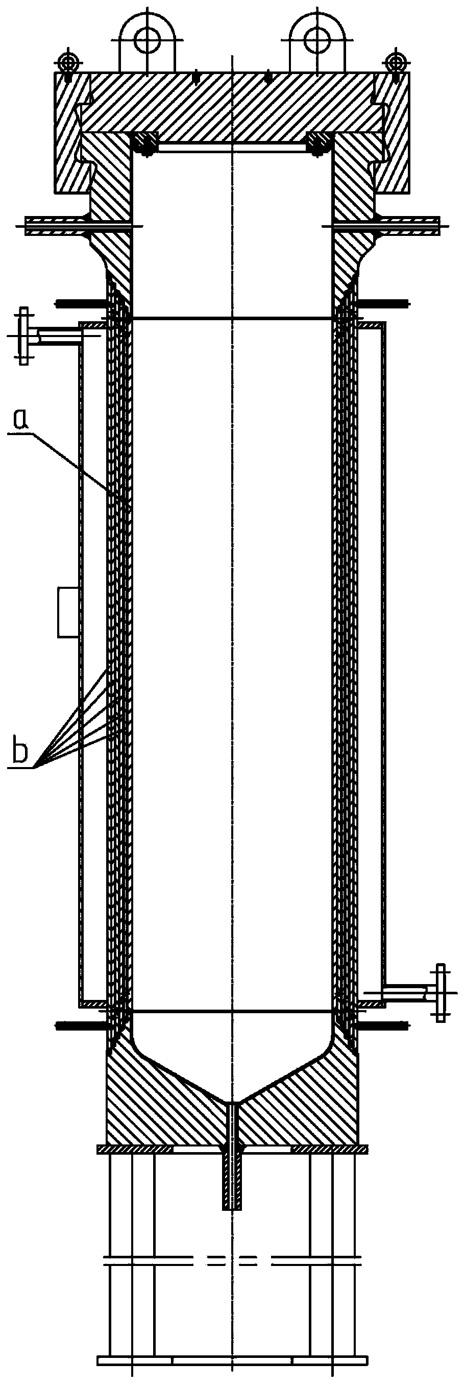
[0077] The extraction unit is divided into two paths, one path is the waste feed pipeline II, the oil-based drilling waste is stored in the waste storage tank 22, and a heating coil is arranged in the waste storage tank 22, and the thermal circulation fluid used for heating in the coil is Provided by the energy recovery balance unit 18, the waste is heated to the set temperature by the heating coil before being added to the extraction kettle, and then fed into the extraction kettle I5a or the extraction kettle II5b by the screw pump 23 respectively (see figure 2 ), the pressure in the extraction kettle is low when feeding, which does not af...


PUM


Abstract

The invention relates to an oil-based drilling waste supercritical treatment system. The oil-based drilling waste supercritical treatment system mainly comprises an extraction unit, a separation unit,an extractant recovery unit and a corresponding control unit. The extraction unit comprises an extraction kettle, an extractant storage tank, a metal diaphragm compressor, an extractant buffer tank,a pre-extraction cooler, a waste storage tank and a screw pump. The separation unit comprises an extraction kettle outlet pipeline switching valve group, a filter, a first-stage pressure reducing valve group, a first-stage separation heater, a first-stage separation kettle, a second-stage pressure reducing valve group, a second-stage separation heater and a second-stage separation kettle; the extractant recovery unit includes a first residual extractant recovery line, a second residual extractant recovery line, an extractant decompression recovery line, and a solute collection line. The systemrealizes the continuous, high-efficient and environmental protection treatment of oil-based drilling waste with high oil content, high water content, high solid content and low fluidity by adjustingand switching the corresponding valves on the pipeline.

Description

technical field [0001] The invention belongs to the technical field of oil-based drilling waste treatment, and in particular relates to a supercritical treatment system for oil-based drilling waste. Background technique [0002] Drilling fluid, also known as drilling mud, is called the "blood" of oil drilling engineering, and its main functions are as follows: [0003] 1. Clean the bottom of the well, suspend and carry cuttings, and keep the wellbore clean; [0004] 2. Balance formation pressure, stabilize well wall, prevent well collapse, blowout and lost circulation; [0005] 3. Transfer water power to help the drill bit break rocks; [0006] 4. Transmitting power for downhole dynamic drilling tools; [0007] 5. Cooling drill bits and drilling tools; [0008] 6. Using drilling fluid for geological and gas logging; [0009] 7. Offshore oil drilling and completion projects, including geology, exploration, cementing, casing running, mud logging, logging, etc., all need t...

Claims


Application Information

Patent Timeline
Patent Type & Authority Applications(China)
IPC IPC(8): C02F11/00C02F103/10
CPCC02F11/002C02F2103/10C02F2301/08C02F2303/10
Inventor 秦宗川王渭廉晓龙郭怀舟张秀平胡继孙范海俊
Owner HEFEI GENERAL MACHINERY RES INST
Learn More