


Quick Research
Generate reliable direction feasibility study reports for your R&D in just a few steps.

Technical Q&A
Discover and master advanced knowledge NOW. Basics, ideas, possibilities, all at once.

Find Solutions
As an expert in R&D theories, this can generate solutions to your technical problems instantly.

Evaluate Feasibility
Analyze your overall solution with one click, know your potential R&D risks in advance.

Monitor Landscape
Get weekly tech updates, stay abreast of the latest tech innovations and key insights.
Automatic plate grooving device and plate grooving machining method thereof
A driving device and plate technology, applied in the manufacturing field of wood processing, can solve the problems of high density of finished plates, deformation of saw blades, low production cost, etc., and achieve the effect of high efficiency and avoiding vibration
- Summary
- Abstract
- Description
- Claims
- Application Information
AI Technical Summary
Problems solved by technology
Method used
Image

Examples
Embodiment 1
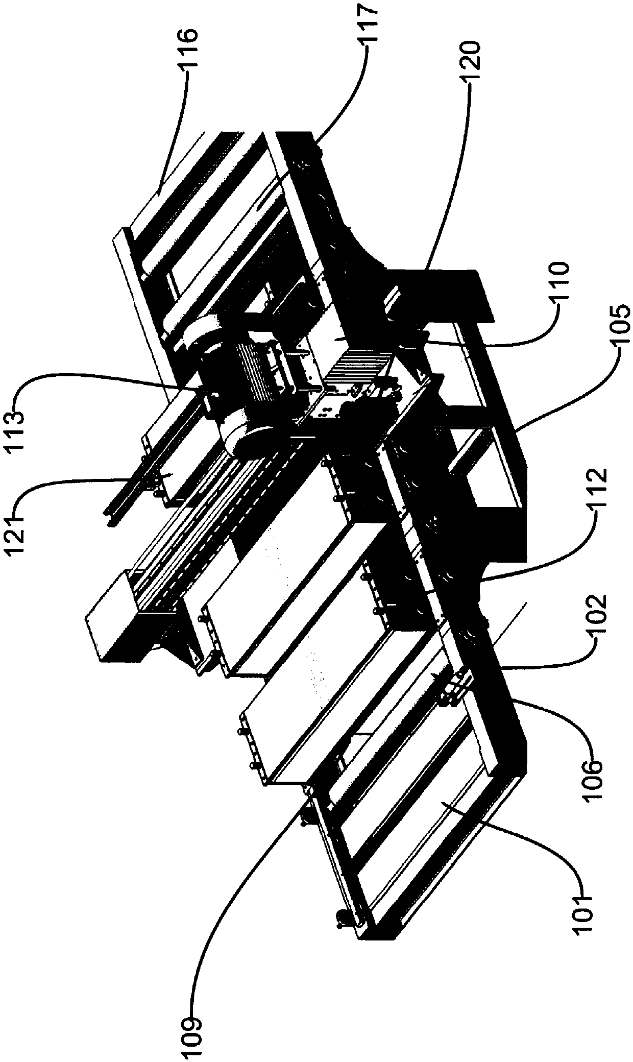
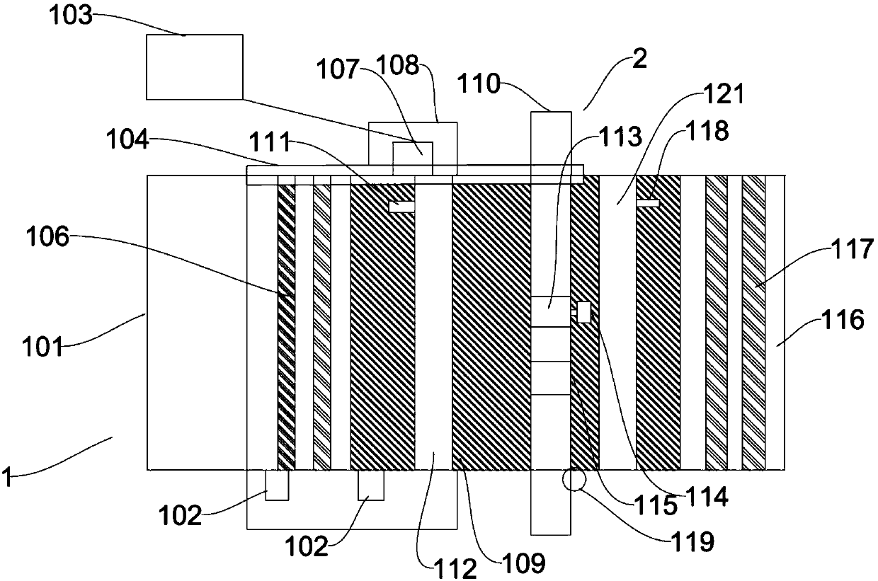
[0056] Specifically, see Figure 2 to Figure 4 , The slotting device includes a workbench (1), a slotting assembly (2), and a PLC control system (103). The slotting group (2) is arranged on the workbench (1), and the workbench (1) is supported by an equipment support (105).
[0057] The slotting assembly (2) comprises a slot saw gantry (110), a second driving device, and a saw blade (114). The second driving device and the saw blade (114) are arranged on the slot saw gantry (110), and the second drive The device is at least capable of driving the saw blade in a translational and / or rotational movement. The second driving device comprises a slot saw step servo motor (115) and a slot saw power motor (113), which are respectively arranged on the slot saw gantry (110), and the slot saw step servo motor (115) controls the saw blade ( 114) translational motion, slot saw power motor (113) controls the rotary motion of saw blade by PLC control system (103).
[0058] The workbench (...
Embodiment 2
[0077] Specifically, see Figure 2 to Figure 4 , the slotting device includes a workbench (1), a slotting assembly (2), and a PLC control system (103). The slotting group (2) is arranged on the worktable (1), and the worktable (1) is supported by an equipment bracket (105).
[0078] The slotting assembly (2) includes a slotting saw gantry (110), a second driving device, and a saw blade (114), the second driving device and the saw blade (114) being arranged on the slotting saw gantry (110), and the first The two driving devices can at least drive the saw blade to perform translational and / or rotational movements. The second driving device includes a slot saw stepping servo motor (115) and a slot saw power motor (113), which are respectively arranged on the slot saw gantry (110). The PLC control system (103) is electrically connected to the second driving device and controls the second driving device.
[0079] The PLC control system (103) controls the slot saw stepping servo ...
Embodiment 3
[0084] Specifically, see Figure 2 to Figure 4 , the slotting device includes a workbench (1), a slotting assembly (2), and a PLC control system (103). The slotting group (2) is arranged on the worktable (1), and the worktable (1) is supported by an equipment bracket (105).
[0085] The slotting assembly (2) includes a slot saw gantry (110), a second drive device, and a saw blade (114), and the second drive device and the saw blade (114) are arranged on the slot saw gantry (110), so The second driving device can at least drive the saw blade to perform translational and / or rotational movement. The second driving device includes a slot saw stepping servo motor (115) and a slot saw power motor (113), which are respectively arranged on the slot saw gantry (110). The PLC control system (103) controls the slot saw stepping servo motor (115) to drive the translational movement of the saw blade (114), and the PLC control system (103) controls the slot saw power motor (113) to contro...
PUM
 Abstract
Description
Claims
Application Information
 - R&D Engineer
- R&D Manager
- IP Professional
- Industry Leading Data Capabilities
- Powerful AI technology
- Patent DNA Extraction
Browse by: Latest US Patents, China's latest patents, Technical Efficacy Thesaurus, Application Domain, Technology Topic, Popular Technical Reports.
© 2024 PatSnap. All rights reserved.Legal|Privacy policy|Modern Slavery Act Transparency Statement|Sitemap|About US| Contact US: help@patsnap.com