
A method of mutual positioning and clamping of micro-nano ends based on 3D imaging feedback

A three-dimensional imaging, positioning and clamping technology, applied in the fields of micro-nano technology and micro-mechanical integration, can solve the problems of low efficiency, low positioning and clamping accuracy, poor effect, etc., and achieve the effect of improving accuracy and positioning accuracy.

Active Publication Date: 2020-04-17
SHANGHAI UNIV
View PDF7 Cites 0 Cited by
  • Summary
  • Abstract
  • Description
  • Claims
  • Application Information

AI Technical Summary

Problems solved by technology

[0003] The purpose of the present invention is to provide a micro-nano terminal mutual positioning and clamping method based on three-dimensional imaging feedback to solve the existing micro-nano terminal positioning and clamping problems of single structure, low efficiency, low positioning and clamping accuracy and poor effect , at the same time, realize the function of mutual positioning and clamping of multi-micro-nano ends, with the advantages of three-dimensional real-time imaging and feedback, and automatic operation

Method used


Image

  • A method of mutual positioning and clamping of micro-nano ends based on 3D imaging feedback
  • A method of mutual positioning and clamping of micro-nano ends based on 3D imaging feedback
  • A method of mutual positioning and clamping of micro-nano ends based on 3D imaging feedback

Examples


Embodiment Construction

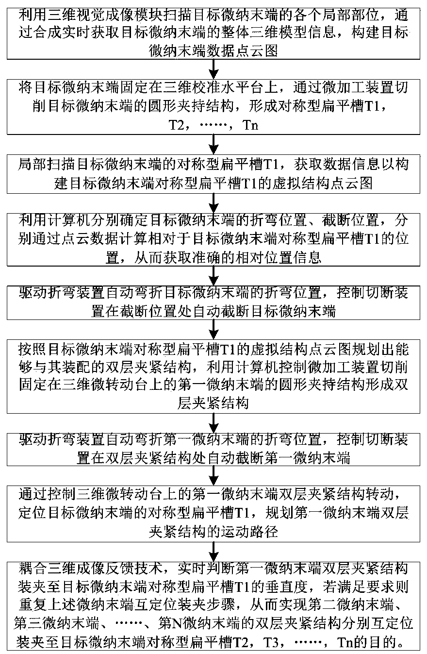
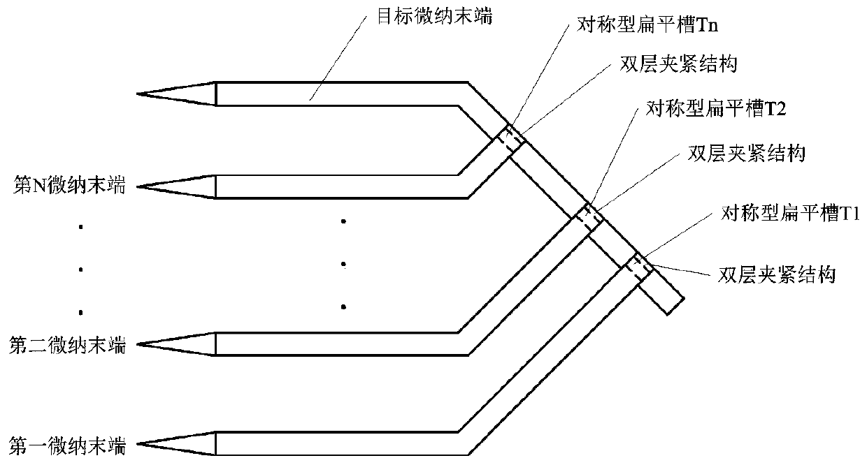
[0035] Such as Figure 1 to Figure 5 As shown, the present invention is based on the three-dimensional imaging feedback micro-nano terminal mutual positioning and clamping method, the specific operation steps are as follows,

[0036] (1) Based on 3D visual imaging, the target micro-nano end is scanned as a whole, the overall 3D model information of the target micro-nano end is obtained, and the point cloud data of the target micro-nano end is constructed.

[0037] (2) Fix the target micro-nano end on the three-dimensional calibration horizontal platform, and use the micro-processing device to symmetrically cut the target micro-nano end to form a symmetrical flat groove; from the blunt end to the tip of the target micro-nano end, at different positions The symmetrical flat grooves formed by cutting are denoted as T1, T2, ..., Tn in sequence. Wherein, each symmetrical flat slot includes two slots symmetrically arranged up and down, and a square snap-in plate 1 is arranged betwe...


PUM


Abstract

The invention belongs to the technical field of micro-nano technologies and micro-electromechanical integration, and particularly relates to a micro-nano tail end mutual positioning and clamping method based on three-dimensional imaging feedback. Based on the three-dimensional vision imaging technology, a micromachining device and the three-dimensional imaging feedback technology, multiple micro-nano tail ends are positioned and clamped at the target micro-nano tail end, the problem that an existing micro-nano tail end positioning and clamping structure is simplex is solved, the method has theadvantage of automatic operation, and the positioning precision of positioning and clamping the micro-nano tail ends is improved; in addition, the bending position and the bending angle of the multiple micro-nano tail ends are controlled, so that the tip ends of the multiple micro-nano tail ends and the tip end of the target micro-nano tail end are positioned on the same straight line or the sameplane, cooperative execution of the multiple micro-nano tail ends is facilitated, and working efficiency is improved.

Description

technical field [0001] The invention belongs to the technical fields of micro-nano technology and micro-electromechanical integration, and in particular relates to a method for mutual positioning and clamping of micro-nano ends based on three-dimensional imaging feedback. Background technique [0002] At present, the micro-nano tip is a common actuator tool in the field of micro-nano research. The simple structure design has obvious economic and practical benefits for applications such as micro-nano operation and measurement. However, for some special occasions, the collaborative execution of multiple micro-nano ends is required, which requires a variety of structural forms of the micro-nano ends. Although the traditional manual micro-nano terminal design method is relatively simple, there are problems such as single structure and low efficiency. In addition, the positioning and clamping of the single micro-nano end is relatively simple. Due to the lack of open-loop control...

Claims


Application Information

Patent Timeline
Patent Type & Authority Patents(China)
IPC IPC(8): B25B11/00
CPCB25B11/00
Inventor 沈斐玲曹宁李恒宇岳涛谢少荣罗均
Owner SHANGHAI UNIV
Learn More