
Grinding device of valve seat of butterfly valve

A technology of grinding device and butterfly valve seat, applied in grinding device, grinding drive device, seat surface grinder, etc., can solve problems such as failure to achieve sealing and leakage, and achieve uniform grinding and good sealing effect.

Pending Publication Date: 2019-11-15
SHANGHAI KOKO VALVE GRP
View PDF8 Cites 8 Cited by
  • Summary
  • Abstract
  • Description
  • Claims
  • Application Information

AI Technical Summary

Problems solved by technology

It forms a sealing pair with the valve seat on the device, and their tight cooperation plays a sealing role. Because 304 stainless steel has a certain toughness, it can make up for the lack of processing accuracy by cooperating with rubber asbestos boards, so it is easy to produce, but his The disadvantage is that it can play a sealing role at the beginning, but it will leak after a short time, and the sealing effect cannot be achieved. This is also a headache for the valve industry. Therefore, a metal-to-metal hard seal is needed. structure, while improving the processing accuracy, it can ensure the shape and position tolerance and roughness of the sealing surface of the valve seat and the disc sealing surface, so that the wear resistance and sealing performance can be maintained in use. For this reason, we need to improve the grinding quality of the valve seat. device

Method used


Image

  • Grinding device of valve seat of butterfly valve
  • Grinding device of valve seat of butterfly valve
  • Grinding device of valve seat of butterfly valve

Examples


Embodiment Construction

[0023] The following will clearly and completely describe the technical solutions in the embodiments of the present invention with reference to the accompanying drawings in the embodiments of the present invention. Obviously, the described embodiments are only some, not all, embodiments of the present invention. Based on the embodiments of the present invention, all other embodiments obtained by persons of ordinary skill in the art without making creative efforts belong to the protection scope of the present invention.

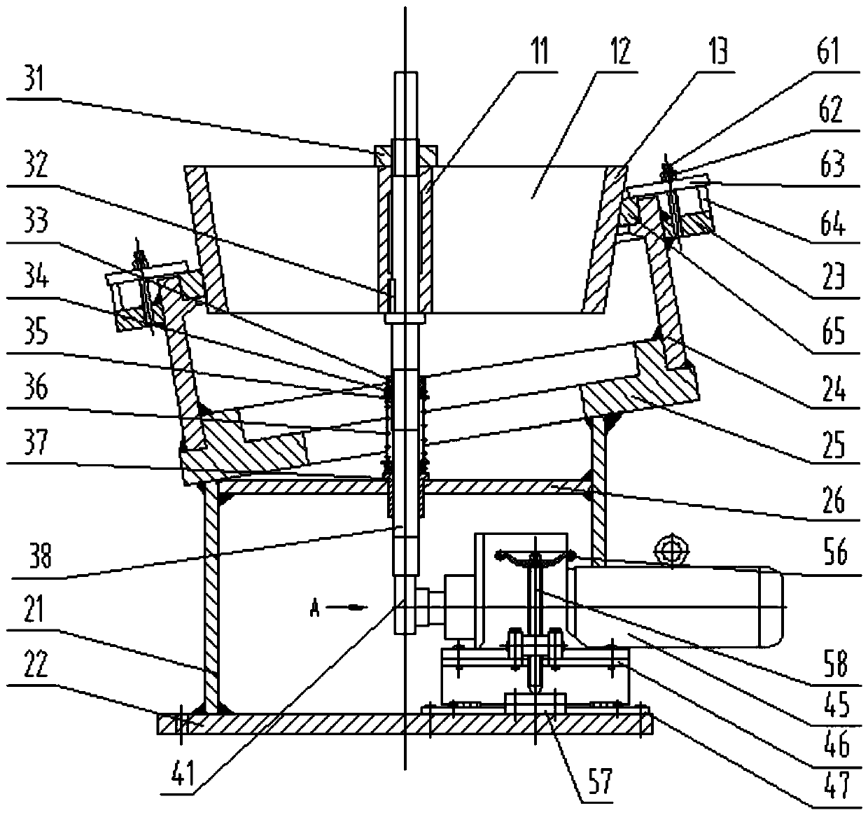
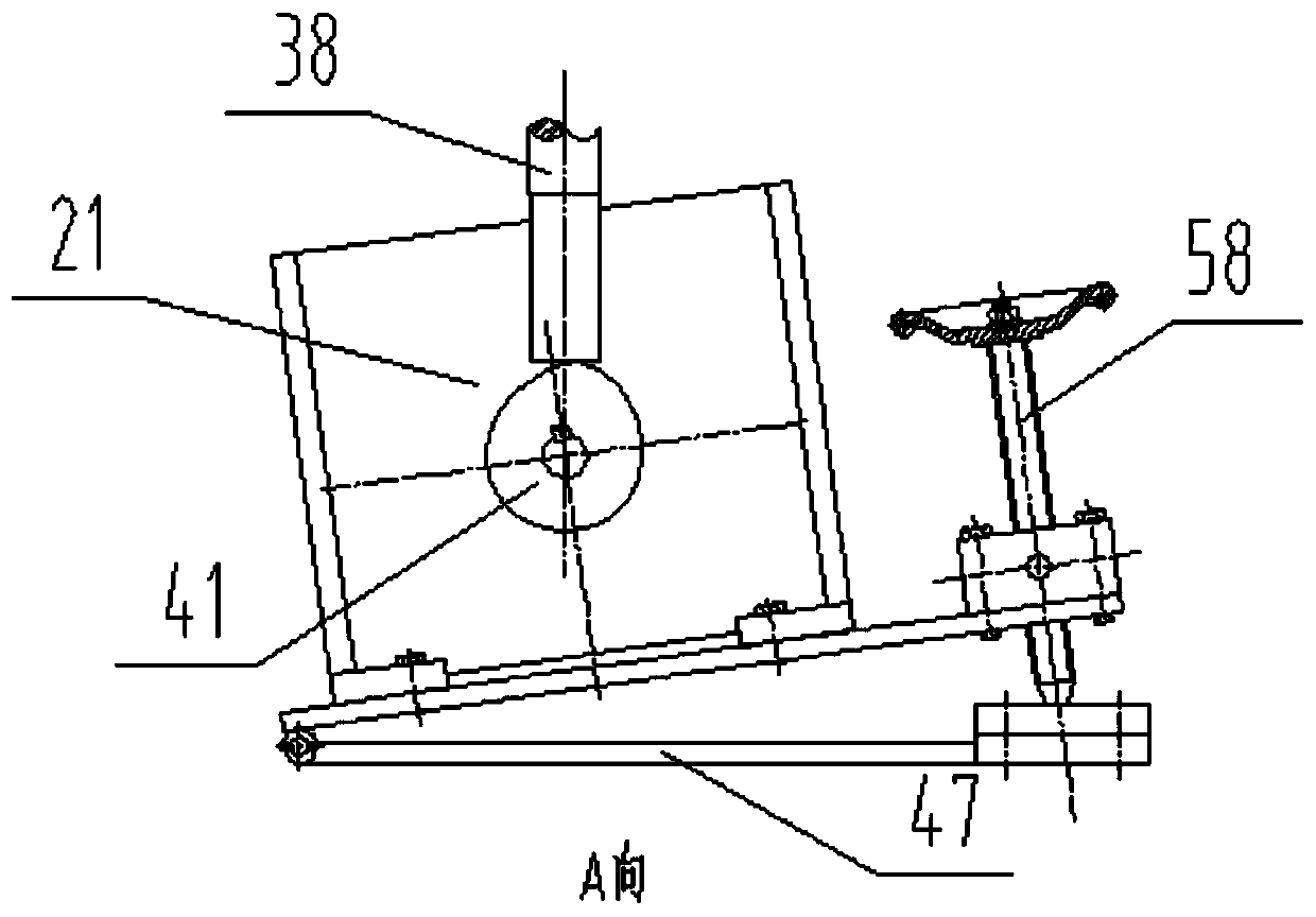
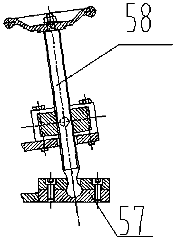
[0024] see Figures 1 to 5 , the present invention provides a technical solution of a butterfly valve seat grinding device: a butterfly valve seat grinding device, comprising a grinding cylinder 13, the grinding surface of the grinding cylinder 13 is on the inner side, and the grinding cylinder 13 is in the shape of an inverted round table with an inner hollow and an upper end opening, And the center of the grinding drum 13 is provided with a main shaft 38 tha...


PUM


Abstract

The invention discloses a grinding device of a valve seat of a butterfly valve. The grinding device comprises a grinding barrel. The grinding barrel is in an inverted circular table shape, wherein theinterior of the inverted circular table shape is hollow, and an opening is formed in the upper end of the inverted circular table shape. A main shaft which is through up and down is arranged in the center of the grinding barrel. A drive head is connected to the upper end of the main shaft, and the main shaft is connected with the grinding barrel through a reinforcing plate. The circumferential lower side of the grinding barrel is in sleeved connection with a valve seat support inclined towards one side. A mounting groove for containing the valve seat is formed in the inner side of the circumferential upper end of the valve seat support, and a valve seat fixing mechanism for fixing the valve seat is arranged on the mounting groove. The main shaft can rotate around a spring, the lower end of the spring is mounted on an upper plate of the support, and a cam mechanism capable of promoting the main shaft to move up and down is mounted on a bottom plate of the support. A speed adjusting motor drives a cam to rotate, and therefore the main shaft is driven to move up and down, the main shaft and the grinding barrel are supported by the spring, and therefore the valve seat moves up and down while rotate circumferentially, the grinding effect is guaranteed, it is guaranteed that grinding of the inner wall of the valve seat is more uniform, and the sealing effect is better.

Description

technical field [0001] The invention relates to the field of butterfly valve seat grinding, in particular to a butterfly valve seat grinding device. Background technique [0002] Butterfly valve hard seal is currently generally used in the industry as the valve seat is made of hard metal, and the multi-layer sealing structure is used on the disc plate. The so-called multi-layer seal is the first layer with 2mm thick 304 stainless steel plate, and the second layer with 2mm thick rubber asbestos board, 2mm thick 304 stainless steel plate for the third layer, 2mm thick rubber asbestos board for the fourth layer, and so on for a total of 9 layers. The specific installation sequence is to put a layer of rubber between every two stainless steel plates. Asbestos board, and then the 9-layer board is clamped on the butterfly plate, and the butterfly plate is fixed on the tooling of the machine tool, and machined according to the designed angle. It forms a sealing pair with the valve...

Claims


Application Information

Patent Timeline
Patent Type & Authority Applications(China)
IPC IPC(8): B24B15/04B24B37/005B24B37/04B24B47/12B24B47/16B24B47/22
CPCB24B15/04B24B37/04B24B47/12B24B37/005B24B47/16B24B47/22
Inventor 张盛洪杨忠义
Owner SHANGHAI KOKO VALVE GRP
Learn More