Back-pull self-centering hydraulic clamp capable of inspecting airtightness
A hydraulic fixture and self-centering technology, applied in the field of hydraulic fixtures, can solve problems such as damage to Morse cone positioning accuracy, loss of fixture accuracy, and scrapped parts.
- Summary
- Abstract
- Description
- Claims
- Application Information
AI Technical Summary
Problems solved by technology
Method used
Image

Examples
Embodiment 1
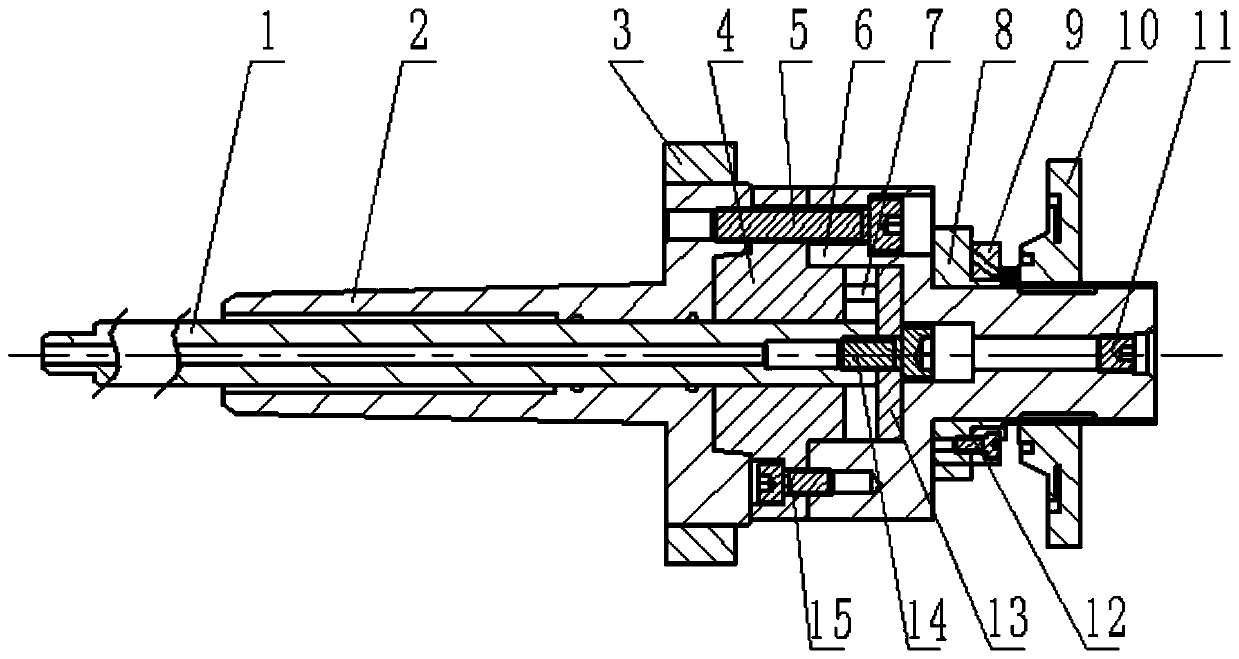
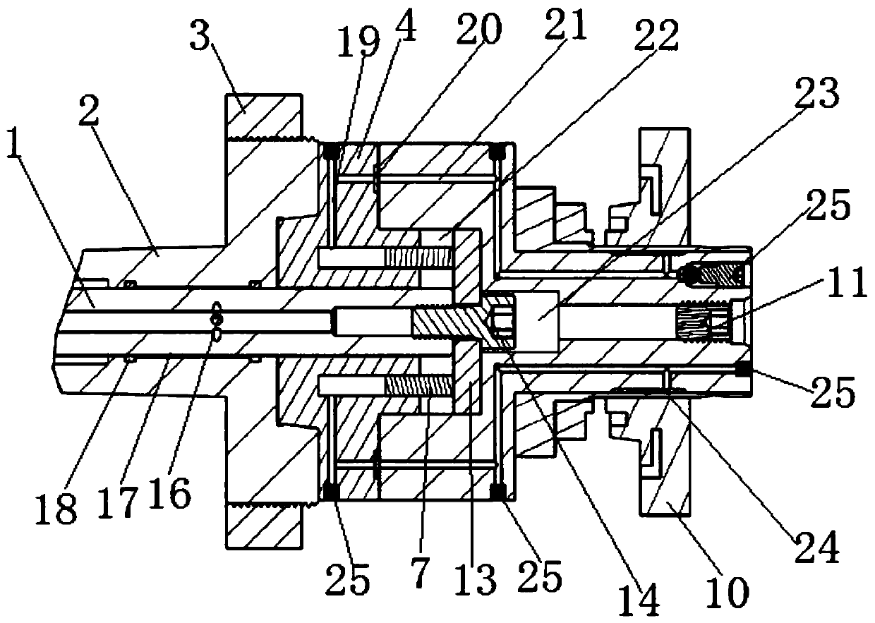
[0044] Such as Figure 1 ~ Figure 3 As shown, a back-pull self-centering hydraulic clamp with airtight detection includes a Morse cone 2, and the side of the Morse cone 2 away from the cone is sequentially connected with an expansion body 4 and a support body 6 ; One side of the expansion body 4 is tightly connected with the Morse cone 2, and the other side is closely connected with the end face of the support body 6 and forms a closed space with the middle part of the support body 6; The end of the body 6 away from the Morse cone 2 is covered with an expansion sleeve 8, and the contact between the support body 6 and the inner hole wall of the expansion sleeve 8 is provided with an annular groove 24, and the annular groove 24 passes through the The oil circuit system is connected to the closed space, and the oil circuit system is sequentially arranged in the support body 6 and the expansion body 4;
[0045] A hollow tie rod 1 is also sleeved in the Morse cone 2, and the tie r...
Embodiment 2
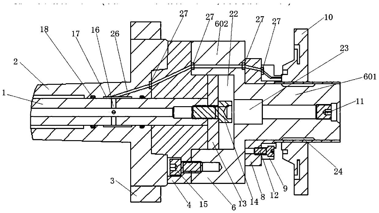
[0067] Such as Figure 1 ~ Figure 3 As shown, a method of using a back-pull self-centering hydraulic clamp with airtight detection, the method of use includes a tightening process and an airtight detection process, the steps are as follows:
[0068] Step (1): Put the workpiece 10 on the expansion sleeve 8, and put the end surface of the workpiece 10 against the end surface of the positioning block 9, and the end of the airtight passage 26 is facing the positioning surface (a part of the end surface) of the workpiece; the machine tool Pull the pull rod 1 to the left, and the pull rod 1 drives the piston disc 13 and the piston 7 to move to the left to compress the oil inside the fixture. sleeve 8, so as to tighten the workpiece 10; wherein the annular groove 24 is within the scope of the inner hole of the workpiece 10;
[0069] Step (2): The gas inside the machine tool is passed into the inner hole of the tie rod 1, and the gas passes through the airtight passage of the Morse c...
Embodiment 3
[0072] When using the back-pull self-centering hydraulic clamp with airtight detection described in Embodiment 1, the positioning block 9 used is matched with the workpiece 10, and the air detection hole (the end of the airtight passage) on the positioning block 9 ) is set to match the end face of the workpiece 10. During assembly, if the wrong workpiece 10 is taken or the hole inserted is wrong, due to the mismatch between the end face and the positioning block 9, it will inevitably lead to air leakage and air tightness detection error, which will cause the machine tool to alarm and remind the workers that the workpiece may be installed incorrectly. Workers select the correct workpiece to install after detection; to a certain extent, the error prevention function is realized to avoid processing the wrong workpiece.
PUM
 Abstract
Description
Claims
Application Information
 - R&D
- Intellectual Property
- Life Sciences
- Materials
- Tech Scout
- Unparalleled Data Quality
- Higher Quality Content
- 60% Fewer Hallucinations
Browse by: Latest US Patents, China's latest patents, Technical Efficacy Thesaurus, Application Domain, Technology Topic, Popular Technical Reports.
© 2025 PatSnap. All rights reserved.Legal|Privacy policy|Modern Slavery Act Transparency Statement|Sitemap|About US| Contact US: help@patsnap.com