
A wiring harness terminal

A technology for connecting terminals and wiring harnesses, applied in the field of electrical equipment, can solve the problems of insufficient wiring efficiency, low installation practicability, wire damage, etc., and achieve the effect of improving wiring efficiency and installation practicability.

Active Publication Date: 2020-11-13
张亚勤
View PDF3 Cites 0 Cited by
  • Summary
  • Abstract
  • Description
  • Claims
  • Application Information

AI Technical Summary

Problems solved by technology

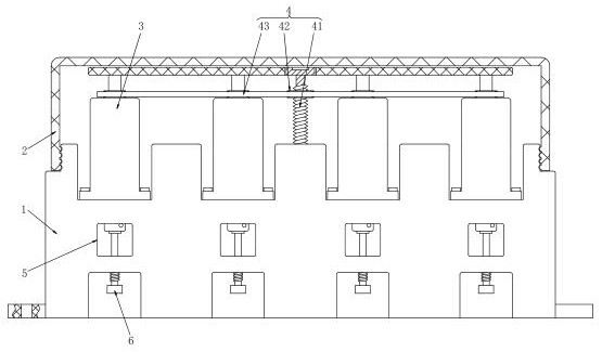
[0003] However, the wire harness terminals in the current market will have the following problems during use. a. The existing wire harness terminals are all locked by screws. On the one hand, the screws directly act on the wires, although they are firmly fixed , but excessive extrusion force is likely to cause damage to the wire. On the other hand, when using screws to fix, the operator needs to twist the copper wire inside the wire into a J shape, and then insert it into the outer wall of the screw to fasten it. Because the terminal The connection between the rows is relatively tight, making it difficult for the copper wire to be socketed on the outer wall of the screw, that is, the installation is less practical; b. The installation of the existing wiring harness terminals is relatively independent, and only one terminal can be connected at a time. The wiring harness is tightened, resulting in no improvement in wiring efficiency

Method used


Image

  • A wiring harness terminal
  • A wiring harness terminal
  • A wiring harness terminal

Examples


Embodiment Construction

[0023] In order to make the technical problems, technical solutions and beneficial effects to be solved by the present invention clearer, the present invention will be further described in detail below in conjunction with the accompanying drawings and embodiments. It should be understood that the specific embodiments described here are only used to explain the present invention, not to limit the present invention.

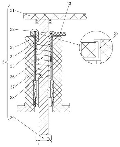
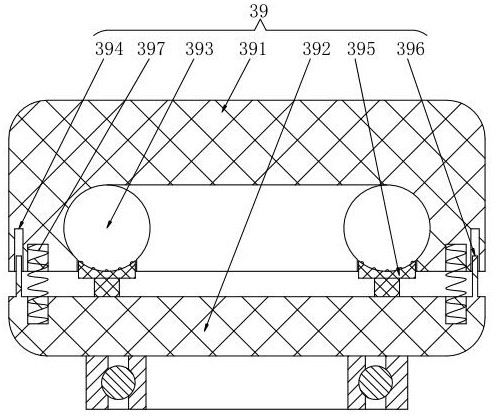
[0024] As shown in 1-5, a wire harness terminal includes a wire base 1, a protective cover 2, a screw assembly 3, a drive assembly 4, a wiring hole 5 and a threaded push rod 6, and the top ends of the wire base 1 are equally spaced. There is an installation slot, the screw assembly 3 is fixed inside the installation slot by bolts, the drive assembly 4 is arranged at the top center of the terminal block 1, and the protective cover 2 is connected to the upper end of the terminal block 1 by a buckle, and the screw assembly 3 and The driving components 4 are all locate...


PUM


Abstract

The invention relates to a wiring harness wiring terminal. The terminal comprises a wire holder, a protective cover, screwing assemblies, driving assemblies, a wiring hole and a threaded push rod. Mounting grooves are formed in the top end of the wire holder at equal intervals. The screwing assemblies are fixed in the mounting grooves through bolts; the driving assemblies are arranged in the center of the top of the wire holder. The protective cover is connected to the upper end of the wire holder through a buckle. The screwing assemblies and the driving assemblies are both located in the protective cover. Wiring holes are formed in a wiring seat and located right below the screwing assemblies; threaded push rods are arranged at the bottom ends of the wiring holes; outer shells are fixed in the mounting grooves through bolts; connecting holes are formed in the centers of the interiors of the outer shells. First connecting threads are formed in the inner walls of the lower ends of the connecting holes, and rotating rods are arranged in the connecting holes; second connecting threads are formed in the outer walls of the bottoms of the rotating rods, and the second connecting threadsand the first connecting threads are of a matched structure.

Description

technical field [0001] The invention relates to the field of electrical equipment, in particular to a wiring harness terminal. Background technique [0002] Wire terminal is an accessory product used to realize electrical connection, which is industrially divided into the category of connectors. With the increasing degree of industrial automation and stricter and more precise industrial control requirements, the amount of terminal blocks is gradually increasing. With the development of the electronics industry, the use of terminal blocks is increasing, and there are more and more types. The wire harness terminal block is one of many terminal blocks, as long as it is used for the connection between wires. [0003] However, the wire harness terminals in the current market will have the following problems during use. a. The existing wire harness terminals are all locked by screws. On the one hand, the screws directly act on the wires, although they are firmly fixed , but exc...

Claims


Application Information

Patent Timeline
Patent Type & Authority Patents(China)
IPC IPC(8): H01R4/14H01R4/38H01R9/00H01R9/22
CPCH01R4/14H01R4/38H01R9/00H01R9/22
Inventor 赵青山李健
Owner 张亚勤
Learn More