
Combustion chamber combustor of gas turbine

A gas turbine and combustion chamber technology, applied in combustion chambers, continuous combustion chambers, combustion methods, etc., can solve the problems of unsuccessful ignition, narrow ignition boundary, and high risk of safe operation, achieve low NOx emissions, improve ignition performance, and optimize classification. effect of effect

Active Publication Date: 2019-11-12
AECC SHENYANG ENGINE RES INST
View PDF4 Cites 2 Cited by
  • Summary
  • Abstract
  • Description
  • Claims
  • Application Information

AI Technical Summary

Problems solved by technology

[0005] 1. Difficulty in ignition: the proportion of air in the head of the existing low-emission combustion chamber burner participating in the ignition process of the combustion chamber is too high, resulting in difficulty in ignition of the burner, narrow ignition boundary, and even unsuccessful ignition
[0006] 2. The control system is complex: the existing low-emission combustor burners have many fuel levels, resulting in a complex control system
[0007] 3. High risk of safe operation: due to the complexity of the control system, it is easy to cause safe operation accidents caused by control system problems

Method used


Image

  • Combustion chamber combustor of gas turbine

Examples


Embodiment Construction

[0024] In order to make the objectives, technical solutions and advantages of the implementation of the application clearer, the technical solutions in the implementation modes of the application will be described in more detail below with reference to the drawings in the implementation modes of the application. In the drawings, the same or similar reference numerals denote the same or similar elements or elements having the same or similar functions throughout. The described embodiments are some, but not all, embodiments of the present application. The embodiments described below by referring to the figures are exemplary and are intended to explain the present application, and should not be construed as limiting the present application. Based on the implementation manners in this application, all other implementation manners obtained by persons of ordinary skill in the art without creative efforts fall within the scope of protection of this application. Embodiments of the pr...


PUM


Abstract

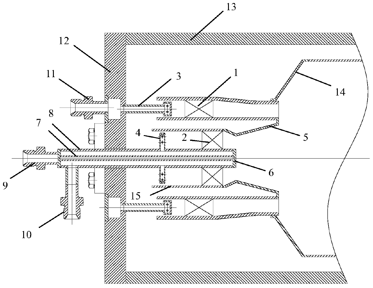
The invention belongs to the technical field of aero-engine design, and relates to a combustion chamber combustor of a gas turbine. A fuel delivery pipeline of the combustion chamber combustor comprises an auxiliary-stage fuel gas pipe at the innermost layer, an auxiliary-stage sleeve, an inner pipe and an outer pipe, wherein the auxiliary-stage sleeve, the inner pipe and the outer pipe are sequentially connected in the radial direction in a sleeve mode, a primary mixing channel is formed between the inner pipe and the outer pipe, and a main-stage swirler is arranged in the main mixing channel; the auxiliary-stage sleeve is connected to the inner wall of the inner pipe through a venturi pipe in a connecting mode, a secondary mixing channel is formed between the auxiliary-stage sleeve and the auxiliary-stage fuel gas pipe, an auxiliary-stage swirler is arranged in the secondary mixing channel, and an auxiliary-stage fuel injection rod extends towards the secondary mixing channel by theauxiliary-stage fuel gas pipe; and a duty-stage fuel gas pipe is arranged in the auxiliary-stage fuel gas pipe in a sleeve mode, and fuel is sprayed in a combustion chamber flame pipe through a duty-stage fuel spraying nozzle. According to the combustion chamber combustor, the two stages axial swirlers, the three stages fuel nozzles and a venturi structure are arranged to realize premixed combustion of the fuel, the grading effect of the head part of the combustion chamber is optimized, the ignition performance of the combustor is improved while low NOx emission is realized, and the complexityof a fuel system is reduced.

Description

technical field [0001] The application belongs to the technical field of aero-engine design, and in particular relates to a gas turbine combustor burner. Background technique [0002] According to the regulations of environmental protection requirements, one of the key requirements for gas turbine combustors is stable and low-emission (mainly for NOx) combustion in a wide range from partial load state to rated load. For the current most mature lean-fuel premixed low-emission combustion technology, the existing burner achieves the requirement of low NOx emission by pre-mixing fuel and air and then feeding it into the combustion zone of the combustion chamber for low-temperature combustion. However, due to the low combustion temperature at partial load, a large amount of unburned hydrocarbon fuel and unburned CO are produced, and problems such as combustion vibration, ignition difficulty, and even flameout occur. [0003] The existing combustor burner technical scheme is that...

Claims


Application Information

Patent Timeline
IPC IPC(8): F23R3/58F23R3/38
CPCF23R3/38F23R3/58
Inventor 张善军马宏宇邵志强
Owner AECC SHENYANG ENGINE RES INST
Learn More