
Nitriding device with adjustable atmosphere area and its continuous gas nitriding process

A gas nitriding, adjustable technology, applied in metal material coating process, solid diffusion coating, coating, etc., can solve problems such as under nitriding or over nitriding

Active Publication Date: 2021-03-19
武汉钢铁有限公司
View PDF16 Cites 0 Cited by
  • Summary
  • Abstract
  • Description
  • Claims
  • Application Information

AI Technical Summary

Problems solved by technology

[0014] The purpose of the present invention is to overcome the deficiencies of the prior art, and provide a nitriding device with adjustable atmosphere area and its continuous gas nitriding process; Gas nitriding process; this method is easy to maintain and easy to operate; it avoids the reduction of nitriding efficiency caused by the premature decomposition of ammonia gas in the high temperature section, and at the same time avoids under-nitriding or over-nitriding caused by the mismatch between the temperature of the sample and the temperature in the nitriding furnace. Nitriding problem

Method used


Image

  • Nitriding device with adjustable atmosphere area and its continuous gas nitriding process
  • Nitriding device with adjustable atmosphere area and its continuous gas nitriding process
  • Nitriding device with adjustable atmosphere area and its continuous gas nitriding process

Examples


Embodiment 1

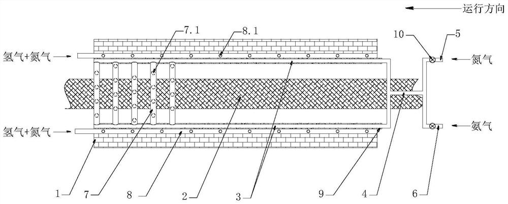
[0044] Such as Figure 1~2 The shown nitriding device with adjustable atmosphere area includes a nitriding chamber 1 (a heating unit is conventionally arranged in the nitriding chamber 1), a conveyor belt 2 is arranged in the nitriding chamber 1, and a conveyor belt 2 is arranged in the nitriding chamber 1. Nitriding gas delivery pipelines 3 are arranged symmetrically above both sides of the belt 2, and the nitriding gas delivery pipelines 3 are placed on the slide rail 9 laid on the side wall of the nitriding chamber 1, and slide back and forth along the slide rail 9; One end of two nitriding gas delivery pipelines 3 protrudes from the inlet end of the nitriding chamber 1 and communicates with a three-way pipe 4. The other end of the three-way pipe 4 communicates with a nitrogen delivery pipeline 5 and an ammonia delivery pipeline 6, and the nitrogen delivery Both the pipeline 5 and the ammonia delivery pipeline 6 are provided with a control valve 10 to control the ratio of n...

Embodiment 2

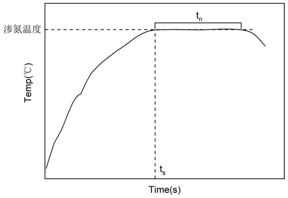
[0059] The length of the nitriding gas delivery pipeline Ll=4100mm, the length of the nozzle area Ln=600mm, adjust the internal temperature of the nitriding chamber according to different nitriding process requirements, and then connect the sample with the thermocouple and pass the plate at the set speed Vs, so that The temperature curve holding platform time tn meets the process requirements. If the temperature and time do not meet the requirements, repeatedly adjust the furnace temperature and measure again until the process requirements are met. According to the measured curve, determine the time ts ( image 3 ), calculate the length Lr of the nitriding tube reserved outside the furnace, manually slide the nitriding gas input pipe, so that the length of the reserved part outside the furnace is equal to Lr, and feed N 2 +NH 3 , the flow rate is fixed, where NH 3 The ratio is greater than 60%, and the nitriding results are shown in Table 1. As a comparison, the comparativ...

Embodiment 3

[0068] Using Examples 1-3 in Example 1 above, the ammonia ratio in the nitriding mixture was adjusted, and the results are shown in Table 2 below. It can be seen from the table that when the ammonia gas ratio exceeds 50%, the nitriding efficiency is significantly improved. When the ammonia gas flow rate is 80%, the nitriding amount is the highest and the efficiency is the best. Table 2 Nitriding results of different ammonia gas ratios

[0069]


PUM


Abstract

The invention discloses an atmospheric area adjustable nitriding device and a continuous gas nitriding process thereof. The device comprises a nitriding cavity, a conveyor belt is arranged in the nitriding cavity, nitriding gas conveying pipelines are symmetrically arranged above two sides of the conveyor belt, a plurality of nitriding spray pipes are arranged between the other ends of the two nitriding gas conveying pipelines, and the nitriding spray pipes are uniformly arranged in a spaced manner on the nitriding gas conveying pipeline; a protecting gas conveying pipeline is arranged on thelateral upper side of the nitriding gas conveying pipelines and is arranged on the side wall of the nitriding cavity, the protecting gas conveying pipeline stretches out from an outlet end of the nitriding cavity, and air outlet holes are uniformly formed in a space manner in the protecting gas conveying pipeline. The method is easy to maintain and simple to operate, prevents decrease of nitridingefficiency as ammonia gas is decomposed too early in a high-temperature segment, and meanwhile, avoids under-nitriding or over-nitriding problem as the temperature of a test sample is not matched with the temperature in a nitriding furnace.

Description

technical field [0001] The invention relates to a production process of oriented silicon steel, in particular to a nitriding device with an adjustable atmosphere area and a continuous gas nitriding process thereof. Background technique [0002] Oriented silicon steel is a soft magnetic material widely used in electric power, electronics, and military industries, and is mainly used to manufacture transformer cores. At present, the methods for industrial production of high magnetic induction oriented silicon steel can be mainly divided into two methods: high-temperature heating of slab and low-temperature heating of slab according to the heating temperature of the slab in the hot-rolling heating furnace. [0003] The main feature of the slab high-temperature heating method is that AlN and MnS or MnSe are the main inhibitors. In order to make MnS or MnSe into a solid solution, the heating temperature of the hot-rolled slab is generally higher than 1320°C, so that the inhibitors...

Claims


Application Information

Patent Timeline
Patent Type & Authority Patents(China)
IPC IPC(8): C23C8/26
CPCC23C8/26
Inventor 孙亮陈圣林高洋吕黎李准杨光郭小龙赵胜利曹阳
Owner 武汉钢铁有限公司
Learn More