Sun gear for boosting bicycle and manufacturing method thereof

A technology for assisting bicycles and a manufacturing method, which is applied to vehicle components, vehicle gearboxes, wheel transmissions, etc., can solve the problems of reduced gear accuracy, large gear runout, low gear tooth profile and tooth direction accuracy, etc., to reduce noise and The effect of vibration, reducing welding workload and eliminating deformation errors

Inactive Publication Date: 2019-11-12
KINETEK DE SHENG SHUNDE MOTOR CO LTD
View PDF12 Cites 1 Cited by
  • Summary
  • Abstract
  • Description
  • Claims
  • Application Information

AI Technical Summary

Problems solved by technology

[0003] 1. The gear forming precision is low, because the gear involute is formed by powder metallurgy die-casting, the tooth shape and direction precision of the gear is very low, reaching the worst level 12 of the national standard;
[0004] 2. After the powder metallurgy die-casting is formed, it needs to be sintered at high temperature, and then carburized and quenched. The deformation caused by heat treatment cannot be eliminated, which further reduces the precision of the gear;
[0005] 3. The flange of the sun gear needs to be finished. At this time, the processing standard is not consistent with the manufacturing standard of the gear involute, which will lead to large gear jump, large noise and vibration of the transmission system, and poor riding experience for customers.

Method used


Image

  • Sun gear for boosting bicycle and manufacturing method thereof
  • Sun gear for boosting bicycle and manufacturing method thereof
  • Sun gear for boosting bicycle and manufacturing method thereof

Examples


Embodiment 1

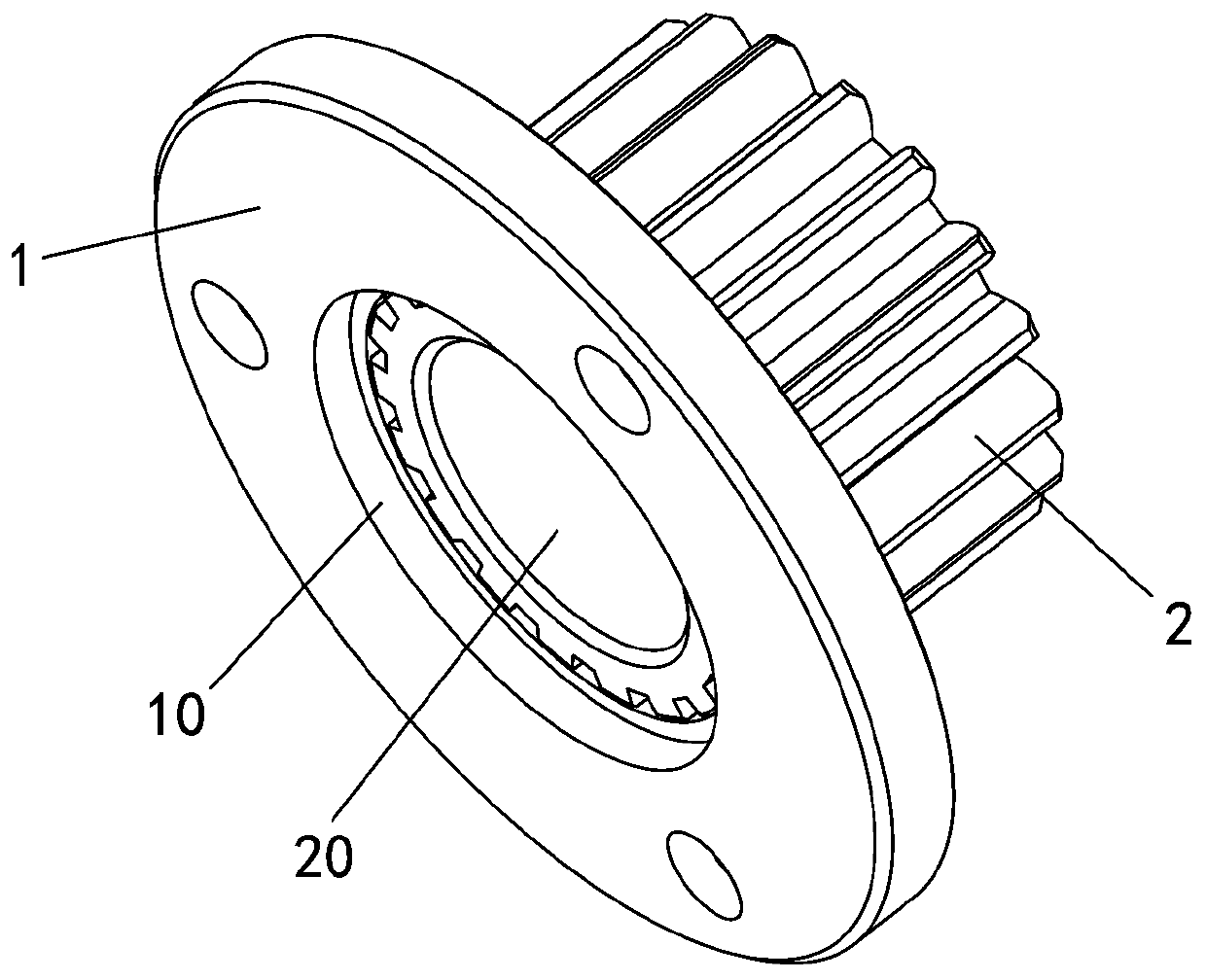
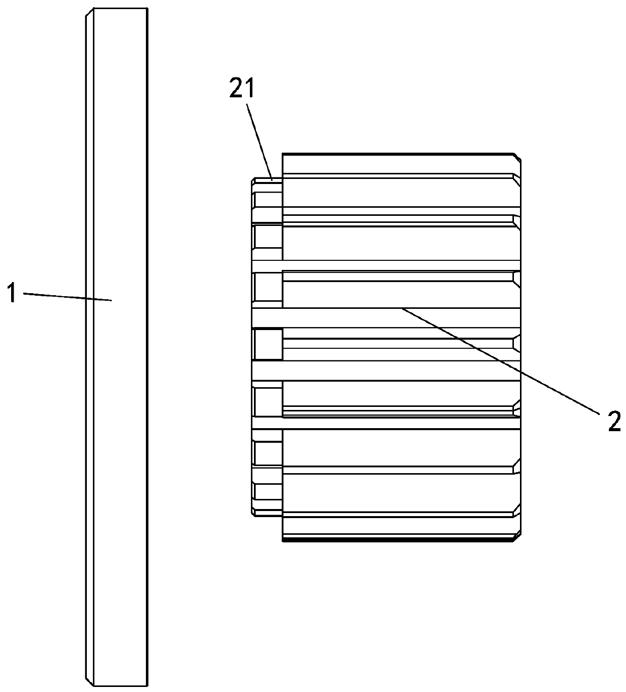
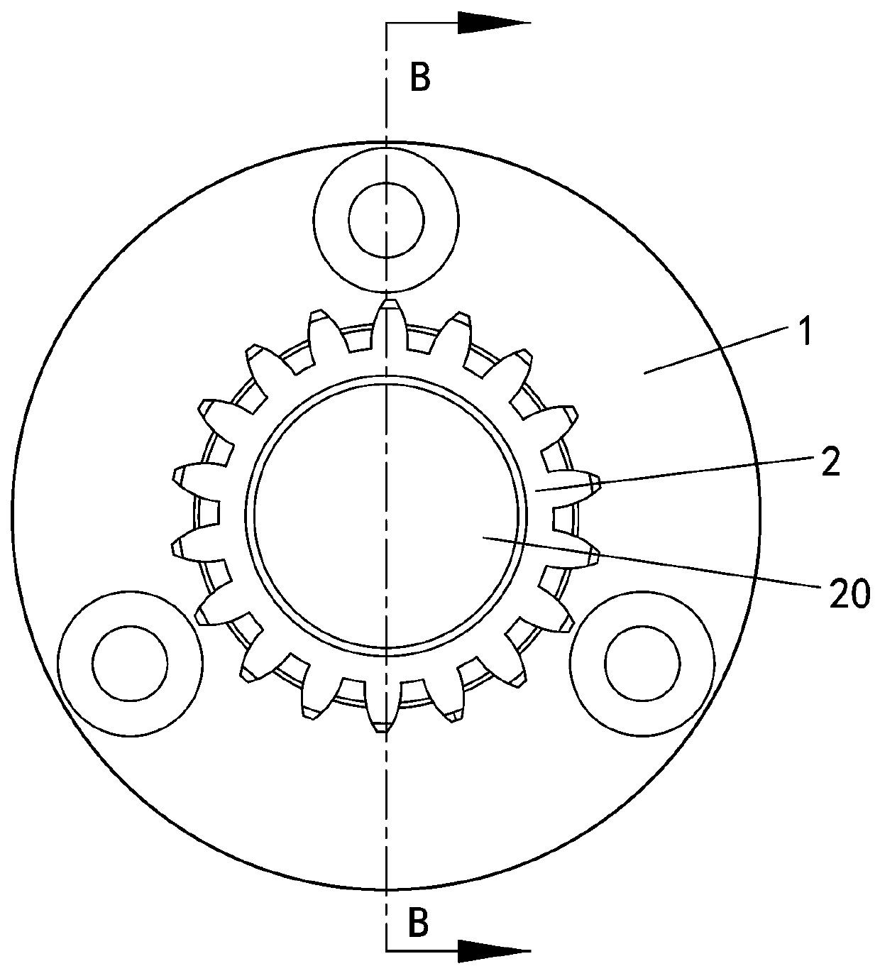
[0029] Embodiment one, see Figure 1 to Figure 4 As shown, a sun wheel for power-assisted bicycles includes a flange 1 and a gear 2. The center of the flange 1 is provided with a stepped hole 10. The stepped hole 10 includes a first section hole 11 and a second section hole. The first section hole The diameter of 11 is greater than the diameter of the second section hole 12, and the thickness of the first section hole 11 and the second section hole 12 are equal; one end of the gear 2 is provided with a step portion 21, and the step portion 21 of the gear 2 is higher than the teeth of the gear 2 On the bottom surface of the groove, the stepped portion 21 of the gear 2 is inserted into the second-stage hole 12, and a welding spot is set between the stepped portion 21 and the end face of the flange 1 close to the second-stage hole 12, so as to weld the flange 1 and the gear 2 into a Sun gear.

[0030] The manufacturing method of the above-mentioned sun gear for power-assisted bi...


PUM


Abstract

The invention discloses a sun gear for a boosting bicycle. The sun gear for the boosting bicycle comprises a flange and a gear; a step hole is formed in the center of the flange; a step part is arranged at one end of the gear; and the step part of the gear is inserted into the step hole to be welded. The sun gear for the boosting bicycle has the advantages that the design is reasonable; the flangeand the gear are assembled, welded and fixed to form the sun gear after being separately and singly machined to improve the machining accuracy of the sun gear; the machining accuracy of the sun gearcan reach the standard; in a sun gear planet gear transmission system, the noises and vibration of the integral gear transmission system are obviously reduced due to the improving of the accuracy; andmeanwhile, as the flange and the gear are in concave-convex fit with each other through the step hole and the step part, the connection is firm and the welding workload is reduced; the position of awelding spot is designed in a concealed manner and does not affect the engagement of the sun gear.

Description

technical field [0001] The invention relates to the technical field of gears, in particular to a sun gear for power-assisted bicycles and a manufacturing method thereof. Background technique [0002] At present, the motor speed reduction mechanisms of mopeds on the market all have a planetary speed reduction structure. The planetary speed reduction structure includes a sun gear, and the sun gear itself has a flange, which is connected to the outer rotor of the motor through the flange. The existing sun gears are all cast by powder metallurgy, the gear and the flange are cast as one, and then the flange is finished. The manufacturing process of this kind of sun gear makes its structure have the following disadvantages: [0003] 1. The gear forming precision is low, because the gear involute is formed by powder metallurgy die-casting, the tooth shape and direction precision of the gear is very low, reaching the worst level 12 of the national standard; [0004] 2. After the p...

Claims


Application Information

Patent Timeline
Patent Type & Authority Applications(China)
IPC IPC(8): B62M11/14B23P15/14
CPCB23P15/14B62M11/14
Inventor 董军黄洁茵叶华琼
Owner KINETEK DE SHENG SHUNDE MOTOR CO LTD
Why Eureka
Try Eureka