High-pressure oil press
A high-pressure oil, press technology, applied in the field of hydraulic presses, can solve the problems of slow speed, low work efficiency, single power source of the press, etc., to prevent deviation, ensure the pressing effect, and prolong the service life.
- Summary
- Abstract
- Description
- Claims
- Application Information
AI Technical Summary
Problems solved by technology
Method used
Image
Examples
Embodiment 1
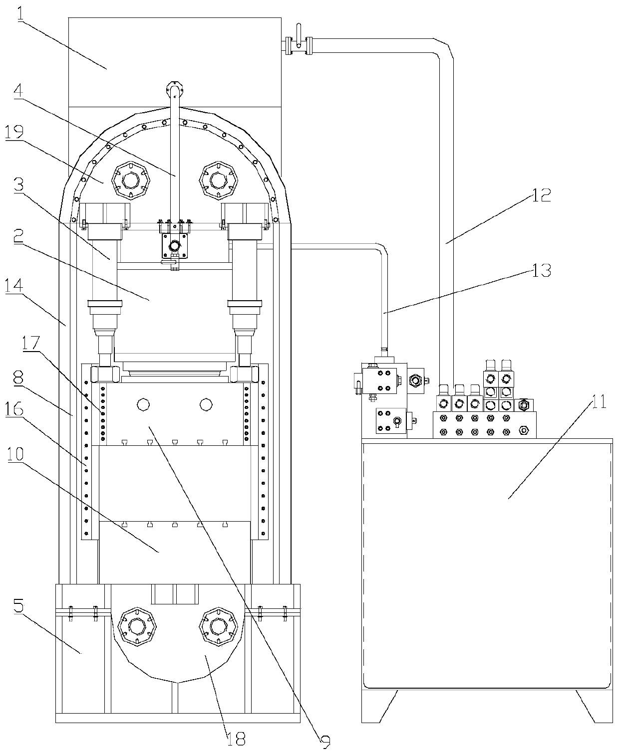
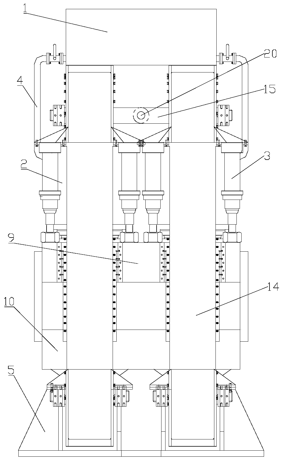
[0040] Such as figure 1 and 2 As shown, a high-pressure hydraulic press includes a frame 14, and a traveler 8 is provided inside the frame 14, and a pressure assembly, a movable beam 9 and a working platform 10 are arranged inside the traveler 8 sequentially from top to bottom.
[0041] The movable beam 9 is connected to the upper end of the traveler 8 through a pressure assembly.
[0042] The pressure assembly includes a pressure oil cylinder 2 and a plurality of hydraulic cylinders 3 .
[0043] The working platform 10 is connected to the lower end of the traveler 8 .
[0044] By setting the traveler 8, when the pressure component is pressurized, the movable beam 9 and the working platform 10 press against both ends of the traveler 8 respectively, and the reaction force of the traveler 8 realizes high-pressure pressing.
Embodiment 2
[0046] Such as figure 1 and 2 As shown, a high-pressure hydraulic press includes a frame 14, and a traveler 8 is provided inside the frame 14, and a pressure assembly, a movable beam 9 and a working platform 10 are arranged inside the traveler 8 sequentially from top to bottom.
[0047] The movable beam 9 is connected to the upper end of the traveler 8 through a pressure assembly.
[0048] The pressure assembly includes a pressure oil cylinder 2 and a plurality of hydraulic cylinders 3 .
[0049] The working platform 10 is connected to the lower end of the traveler 8 .
[0050] By setting the traveler 8, when the pressure component is pressurized, the movable beam 9 and the working platform 10 press against both ends of the traveler 8 respectively, and the reaction force of the traveler 8 realizes high-pressure pressing.
[0051] The hydraulic cylinder 3 is provided with four, and the four hydraulic cylinders 3 are centered and symmetrically distributed with the axis of the p...
Embodiment 3
[0061] Such as figure 1 and 2 As shown, a high-pressure hydraulic press includes a frame 14, and a traveler 8 is provided inside the frame 14, and a pressure assembly, a movable beam 9 and a working platform 10 are arranged inside the traveler 8 sequentially from top to bottom.
[0062] The movable beam 9 is connected to the upper end of the traveler 8 through a pressure assembly.
[0063] The pressure assembly includes a pressure oil cylinder 2 and a plurality of hydraulic cylinders 3 .
[0064] The working platform 10 is connected to the lower end of the traveler 8 .
[0065] By setting the traveler 8, when the pressure component is pressurized, the movable beam 9 and the working platform 10 press against both ends of the traveler 8 respectively, and the reaction force of the traveler 8 realizes high-pressure pressing.
[0066] The hydraulic cylinders 3 are provided with four, and the four hydraulic cylinders 3 are symmetrically distributed around the axis of the pressure...
PUM
 Abstract
Description
Claims
Application Information
 - R&D
- Intellectual Property
- Life Sciences
- Materials
- Tech Scout
- Unparalleled Data Quality
- Higher Quality Content
- 60% Fewer Hallucinations
Browse by: Latest US Patents, China's latest patents, Technical Efficacy Thesaurus, Application Domain, Technology Topic, Popular Technical Reports.
© 2025 PatSnap. All rights reserved.Legal|Privacy policy|Modern Slavery Act Transparency Statement|Sitemap|About US| Contact US: help@patsnap.com


