
Processing method for inner hole of cylinder block

A processing method and inner hole technology, applied in the field of mechanical processing, can solve the problems of insufficient processing accuracy, affecting the use of hydraulic lifts, oil leakage, etc., and achieve the effects of improving stability and sealing, and reducing the processing scrap rate.

Active Publication Date: 2019-11-12
WUHAN MARINE MACHINERY PLANT
View PDF5 Cites 2 Cited by
  • Summary
  • Abstract
  • Description
  • Claims
  • Application Information

AI Technical Summary

Problems solved by technology

[0002] The cylinder body is an important part of the hydraulic lift. If the machining accuracy of the inner hole to be processed is not enough, the sealing of the inner hole to be processed will not be tight, resulting in oil leakage.
The surface quality of the inner hole to be processed is not enough, which will cause the wear of the inner hole to exceed the standard. At the same time, due to the insufficient surface accuracy, the processed thread line on the surface of the inner hole to be processed will cause a certain rotation when the cylinder is raised and lowered, which will seriously affect the use of the hydraulic lift.
[0003] The traditional processing method of the inner hole to be processed is usually processed by the technician based on the experience of the inner hole to be processed. For example, the processing steps during processing, the processing tools used in each processing step, and the processing accuracy of each step. Mechanics choose based on experience and have not formed a certain theoretical experience. For inexperienced mechanics, the machining accuracy and surface quality of the inner hole to be processed often do not meet the requirements due to lack of experience, resulting in the scrapping of the cylinder body. higher rate

Method used


Image

  • Processing method for inner hole of cylinder block
  • Processing method for inner hole of cylinder block
  • Processing method for inner hole of cylinder block

Examples


Embodiment Construction

[0037] In order to make the object, technical solution and advantages of the present invention clearer, the implementation manner of the present invention will be further described in detail below in conjunction with the accompanying drawings.

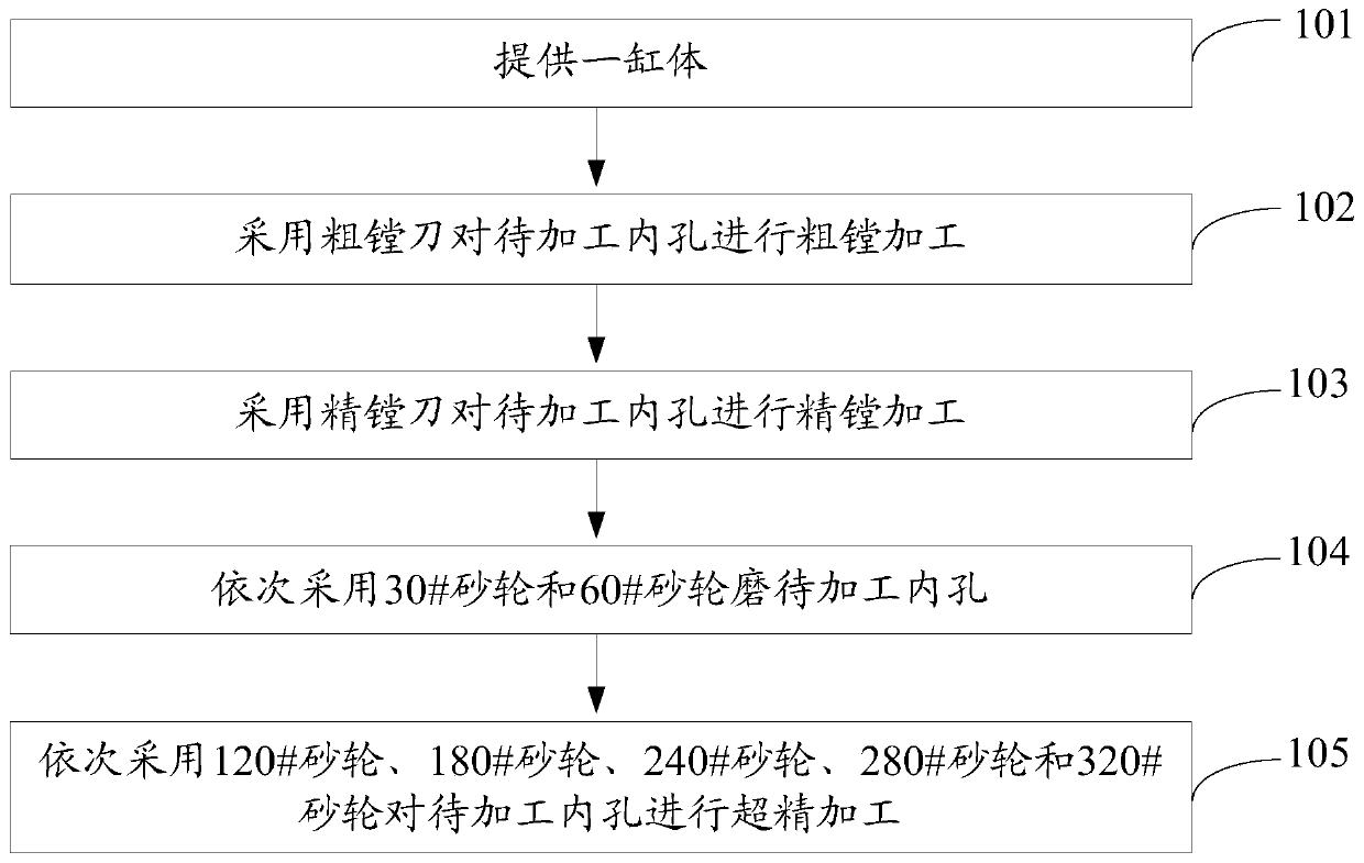
[0038] figure 1 It is a flow chart of a machining method for a cylinder bore provided by an embodiment of the present invention, as shown in figure 1 As shown, the processing method includes:

[0039] Step 101, providing a cylinder.

[0040] Wherein, the cylinder body can be made of quenched and tempered carbon steel.

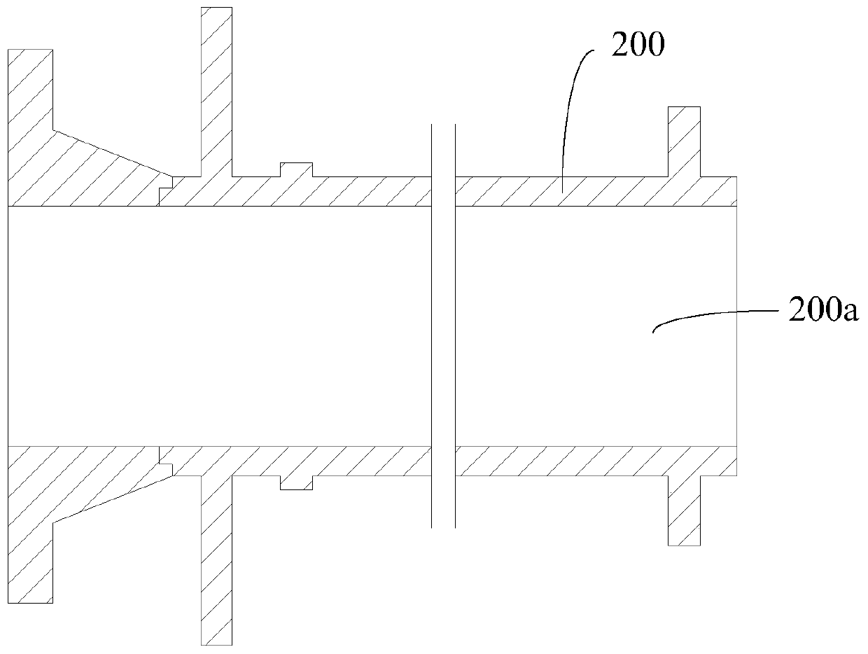
[0041] figure 2 It is a structural schematic diagram of a cylinder body provided by an embodiment of the present invention, such as figure 2 As shown, the central part of the cylinder body 200 is provided with an inner hole 200a to be processed.

[0042] Step 102, using a rough boring tool to rough bore the inner hole to be machined.

[0043] Among them, the surface roughness of the inner hole to be processed af...


PUM

PropertyMeasurementUnit
Cylindricityaaaaaaaaaa

Abstract

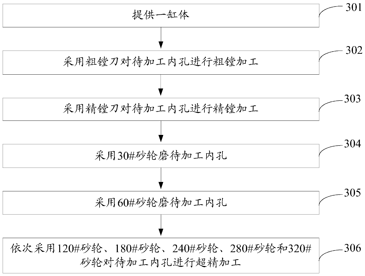
The invention discloses a processing method for an inner hole of a cylinder block and belongs to the technical field of machining. The processing method comprises the following steps: providing a cylinder block with a to-be-processed inner hole; carrying out heavy boring processing on the to-be-processed inner hole by using a heavy boring cutter; carrying out fine boring processing on the to-be-processed inner hole by using a fine boring cutter; grinding the to-be-processed inner hole by using a 30# grinding wheel and a 60# grinding wheel successively; and carrying out superfinishing processing on the to-be-processed inner hole by using a 120# grinding wheel, a 180# grinding wheel, a 240# grinding wheel, a 280# grinding wheel and a 320# grinding wheel successively to obtain the inner holeof the cylinder block needed to be processed, wherein the surface roughness of the processed inner hole of the cylinder block is not smaller than Ra0.2 and the cylindricity is not smaller than 0.02 mm. By adopting the processing method for the inner hole of the cylinder block, the processing precision and the surface quality of the to-be-processed inner hole can be improved, so that the processingrejection rate of the cylinder block is reduced.

Description

technical field [0001] The invention relates to the technical field of mechanical processing, in particular to a processing method of a cylinder bore Background technique [0002] The cylinder body is an important part of the hydraulic lift. If the machining accuracy of the inner hole to be processed is not enough, the sealing of the inner hole to be processed will not be tight, resulting in oil leakage. The surface quality of the inner hole to be processed is not enough, which will cause the wear of the inner hole to exceed the standard. At the same time, due to the insufficient surface accuracy, the processed thread line on the surface of the inner hole to be processed will cause a certain rotation when the cylinder is raised and lowered, which will seriously affect the use of the hydraulic lift. . [0003] The traditional processing method of the inner hole to be processed is usually processed by the technician based on the experience of the inner hole to be processed. F...

Claims


Application Information

Patent Timeline
Patent Type & Authority Applications(China)
IPC IPC(8): B23P17/00
CPCB23P17/00
Inventor 潘文鼎佘邵平袁鹏
Owner WUHAN MARINE MACHINERY PLANT
Learn More