
Double-sided radiation acoustic exciter

A technology of radiating sound and exciter, which is applied in the direction of sensors, TVs, color TV parts, etc., can solve the problem of inability to enhance the sense of low-frequency volume and low-frequency radiation quality, limited speaker unit structure and installation position, and inability to further reduce the thickness of the whole machine and other problems, to achieve the effect of improving the sense of hearing, bearing high power, and meeting the requirements of use

Pending Publication Date: 2019-11-08
WUXI JIEFU ELECTROACOUSTIC
View PDF0 Cites 3 Cited by
  • Summary
  • Abstract
  • Description
  • Claims
  • Application Information

AI Technical Summary

Problems solved by technology

[0002] In the prior art, in order to improve the sound quality of thin and large TVs such as OLED and ULED, multiple speaker units are generally used to form a sound box to improve the low-frequency response characteristics, but this type of sound system is usually limited by the structure and installation position of the speaker unit , and the thickness of the whole structure of the TV set, it is impossible to further enhance the sense of volume of low frequency and the quality of low frequency radiation on the premise of thinning
Since the speaker cone radiates sound, it is necessary to ensure that a certain cavity is reserved in front of the cone to facilitate the cone to push the air, so that the entire application scene requires a large space, and the thickness of the whole machine cannot be further reduced.
Although the traditional exciter abandons the sound cone structure and can reduce the space requirements for the whole machine when installed on a flat-panel TV, it can only radiate sound from one side, and cannot radiate sound with high sound pressure level at higher power , in order to reduce the thickness of the product as much as possible on the premise of ensuring the acoustic characteristics to meet the use requirements of the end product, a new type of transducer that can radiate sound with high power is urgently needed

Method used


Image

  • Double-sided radiation acoustic exciter
  • Double-sided radiation acoustic exciter
  • Double-sided radiation acoustic exciter

Examples


Embodiment Construction

[0021] The present invention will be further described below in conjunction with specific drawings and embodiments.

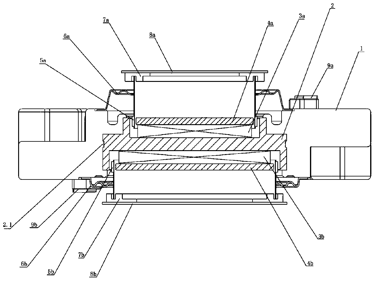
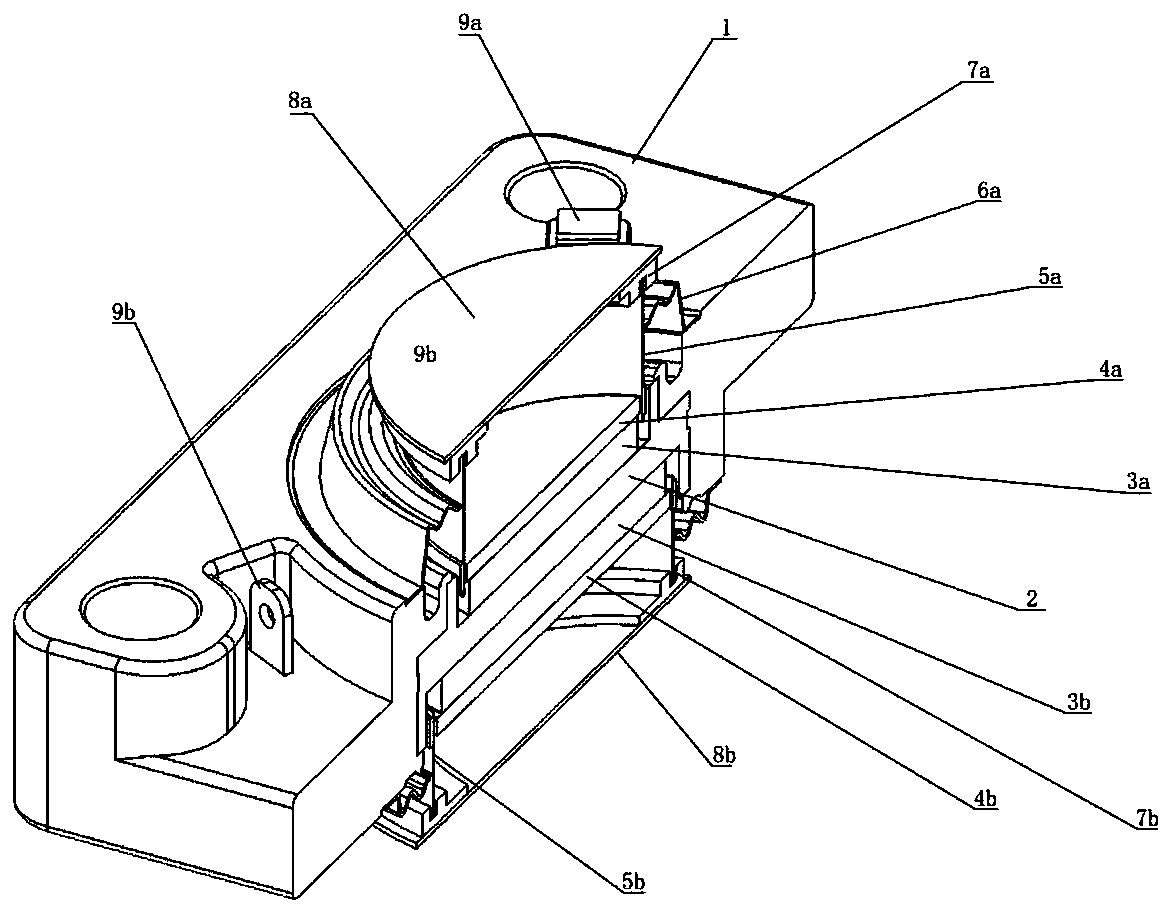
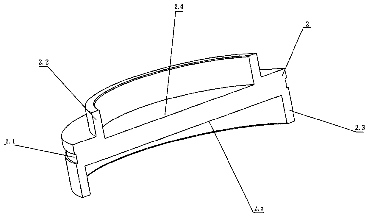
[0022] Such as Figure 1~Figure 4 As shown, the double-sided radiation acoustic exciter in the embodiment includes a pot frame 1, a bidirectional magnetic yoke 2, a first magnet 3a, a first magnetic pole core 4a, a first voice coil 5a, a first positioning strut 6a, a first The bearing ring 7a, the first flat plate 8a, the first terminal post 9a, the second magnet 3b, the second magnetic pole core 4b, the second voice coil 5b, the second positioning strut 6b, the second bearing ring 7b, and the second flat plate 8b , the second terminal 9b, the bidirectional guide yoke 2 is embedded in the pot frame 1;

[0023] A first magnet 3a is arranged directly above the first bottom 2.4 on one side of the bidirectional guide yoke 2, and a first magnetic pole core 4a is arranged directly above the first magnet 3a. On the first inner wall 2.2 of the bidirectional guide yoke...


PUM


Abstract

The invention relates to a double-sided radiated sound exciter. The exciter comprises a basin stand, a bidirectional conductive magnet, a first magnet, a first magnetic pole core, a first voice coil,a first positioning support chip, a first bearing ring, a first flat plate, a first binding post, a second magnet, a second magnetic pole core, a second voice coil, a second positioning support chip,a second bearing ring, a second flat plate and a second binding post. On the premise that the thickness of the exciter is low, the exciter can push the two flat plates to radiate sound in two directions at the same time through the two bidirectional magnetic circuit systems, the exciter is suitable for being directly attached to a glass screen and a rear machine shell of a high-grade thin television such as an OLED to be used, and the glass screen and the rear machine shell of the television can be pushed to produce sound at the same time.

Description

technical field [0001] The invention relates to the technical field of electroacoustics, in particular to a double-sided radiation acoustic exciter. Background technique [0002] In the prior art, in order to improve the sound quality of thin and large TVs such as OLED and ULED, multiple speaker units are generally used to form a sound box to improve the low-frequency response characteristics, but this type of sound system is usually limited by the structure and installation position of the speaker unit , and the thickness of the whole structure of the TV set, it is impossible to further enhance the low-frequency sense of volume and low-frequency radiation quality under the premise of thinning. Since the speaker cone radiates sound, it is necessary to ensure that a certain cavity is reserved in front of the cone to facilitate the cone to push the air, so that the entire application scene requires a large space, and the thickness of the whole machine cannot be further reduced...

Claims


Application Information

Patent Timeline
Patent Type & Authority Applications(China)
IPC IPC(8): H04R9/02H04R9/06H04N5/64
CPCH04R9/02H04R9/06H04N5/642
Inventor 蒋加星吴晓军蔡禄军
Owner WUXI JIEFU ELECTROACOUSTIC
Learn More