
Broadband high-reliability piezoelectric beam coupled energy collection device

A technology of energy harvesting and piezoelectric beams, applied in the direction of piezoelectric effect/electrostrictive or magnetostrictive motors, electrical components, generators/motors, etc., can solve the inherent defects of no power supply, structural reliability, piezoelectric Beam fatigue fracture and other problems, to prevent root fracture, improve mechanical environment adaptability, and avoid destructive deformation

Active Publication Date: 2019-11-08
BEIJING CTROWELL INFRARED TECHN +1
View PDF8 Cites 5 Cited by
  • Summary
  • Abstract
  • Description
  • Claims
  • Application Information

AI Technical Summary

Problems solved by technology

[0002] At present, there is no power supply for railway freight train carriages. If it is necessary to monitor the state of the freight carriages during travel, the sensor terminals installed in the carriages need to solve the power supply problem by themselves; according to the fact that the wheel-rail contact of the carriages can provide continuous vibration energy during travel One feature, the collection of vibration energy provides a solution to the power supply problem of the sensor. The vibration energy harvesting device based on the piezoelectric cantilever structure has been widely studied because it can provide large strain design and high charge output. In practical engineering applications, there are often large impact loads acting on the piezoelectric beam structure, and the root of the piezoelectric beam is prone to fatigue fracture, which has inherent defects in structural reliability.

Method used


Image

  • Broadband high-reliability piezoelectric beam coupled energy collection device

Examples


Embodiment Construction

[0022] The present invention will be described in further detail below in conjunction with the accompanying drawings.

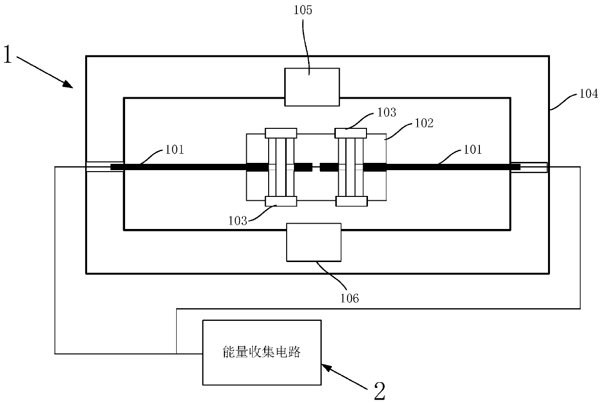
[0023] The present invention relates to a piezoelectric beam coupled energy collection device with high reliability and wide frequency, which is composed of two parts: an electric energy conversion module 1 and an energy collection module 2 . Among them, the energy conversion module 1 is composed of a piezoelectric beam coupling energy collection structure and a magnetic field structure. The piezoelectric beam coupling energy harvesting structure is composed of a piezoelectric beam 101 , a shared mass 102 , a limit bolt 103 and a housing 104 . The magnetic field structure is composed of an upper permanent magnet 105 , a lower permanent magnet 106 and a shared mass 102 .

[0024] The casing 104 has a cubic structure, and the piezoelectric beam installation holes opened at the center of the left and right side walls of the casing 104 are used for installing th...


PUM


Abstract

The invention discloses a broadband high-reliability piezoelectric beam coupled energy collection device, which is formed by a plurality of piezoelectric beams arranged in the housing. The opposite ends of the piezoelectric beams are connected through a mass block made of a ferromagnetic material and a limit bolt to control large deformation under over-impact load. The housing is internally provided with a permanent magnet, which produces a magnetic field at the place of the mass block to form a piezoelectric magneto-elastic structure. Under the external vibration loading condition, the vibration energy is transferred to the housing, which makes the piezoelectric beams generate nonlinear vibration perpendicular to the piezoelectric beams, so that wideband energy collection is realized. Thetail ends of the piezoelectric beams are connected to an energy collection module, and the energy collection module collects electric charges generated by vibration of the piezoelectric beams. The device has the characteristics of large strain, wide response frequency and high charge output of the piezoelectric beams, as well as reliability of the structure in the vibration energy collection process, thereby not only ensuring efficient vibration energy collection, but also ensuring long-term reliable and stable working condition of the structure.

Description

technical field [0001] The invention relates to an energy harvesting device, in particular to a broadband and high reliability piezoelectric beam coupling energy harvesting device. Background technique [0002] At present, there is no power supply for railway freight train carriages. If it is necessary to monitor the state of the freight carriages during travel, the sensor terminals installed in the carriages need to solve the power supply problem by themselves; according to the fact that the wheel-rail contact of the carriages can provide continuous vibration energy during travel One feature, the collection of vibration energy provides a solution to the power supply problem of the sensor. The vibration energy harvesting device based on the piezoelectric cantilever structure has been widely studied because it can provide large strain design and high charge output. In practical engineering applications, there are often large impact loads acting on the piezoelectric beam struc...

Claims


Application Information

Patent Timeline
Patent Type & Authority Applications(China)
IPC IPC(8): H02N2/18
CPCH02N2/186
Inventor 孙超陈曦周毛毛殷延超公茂财农时猛
Owner BEIJING CTROWELL INFRARED TECHN
Learn More