Cycloolefin copolymer micro-lens array with metal diaphragm and preparation method thereof
A technology of cycloolefin copolymer and microlens array, which is applied in the direction of lens, optomechanical equipment, photoplate making process of pattern surface, etc. It can solve the difficult problem of optical microlens dimensional accuracy and shape, and the complex processing and integration of matching aperture , high processing costs and other issues, to achieve good array uniformity and repeatability, cost and time saving, and short processing time
- Summary
- Abstract
- Description
- Claims
- Application Information
AI Technical Summary
Benefits of technology
Problems solved by technology
Method used
Image


Examples
preparation example Construction
[0048] The invention provides a cycloolefin copolymer microlens array with a metal diaphragm and a preparation method thereof.
[0049] In a first aspect, the present invention provides a cycloolefin copolymer microlens array with a metal diaphragm, comprising the steps of:
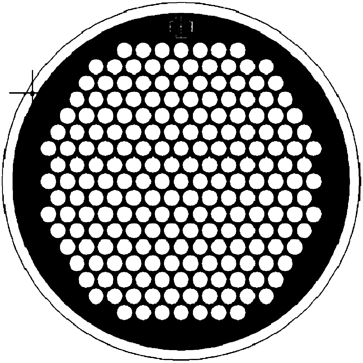
[0050] S101, using the first photolithography mask to form a first photoresist mask with a microlens array pattern on the surface of the silicon wafer substrate by photolithography;
[0051] S102, using an etching method to etch the first photoresist mask to etch a silicon wafer microhole array on the silicon wafer substrate;
[0052] S103. After paving the cycloolefin copolymer layer on the micropore array of the silicon chip, heat and press, cool, separate the micropore array of the silicon chip from the cycloolefin copolymer layer, and invert the cycloolefin copolymer layer to obtain the first cycloolefin copolymer arrays;
[0053] S104. Using a second photolithography mask to form a second photoresi...
Embodiment 1
[0070] The method for preparing the cycloolefin copolymer microlens array with metal diaphragm provided by the present invention may specifically comprise the following steps:
[0071] (1) Spin-coat positive photoresist on the surface of the silicon wafer substrate, use the first photolithography mask to expose and develop, and form a patterned first photoresist mask on the surface of the silicon wafer substrate, the first photolithography The patterns on the glue mask are photoresist microlens array patterns.
[0072] (2) by dry etching the silicon wafer substrate with the first photoresist mask, form the same diameter with the photoresist microlens array pattern diameter on the silicon wafer substrate with the first photoresist mask Microhole arrays on silicon wafers, and passivation treatment on the surface of microhole arrays on silicon wafers.
[0073] (3) Put the cycloolefin copolymer and the passivated silicon wafer micropore array into a hot press, place a spacer ring...
Embodiment 2
[0080] The method for preparing the cycloolefin copolymer microlens array with metal diaphragm provided by the present invention may specifically comprise the following steps:
[0081] (1) Spin-coat positive photoresist on the surface of the silicon wafer substrate, use the first photolithography mask to expose and develop, and form a patterned first photoresist mask on the surface of the silicon wafer substrate, the first photolithography The patterns on the glue mask are photoresist microlens array patterns.
[0082] (2) by dry etching the silicon wafer substrate with the first photoresist mask, form a diameter identical to the photoresist microlens array pattern diameter on the silicon wafer substrate with the first photoresist mask Microhole arrays on silicon wafers, and passivation treatment on the surface of microhole arrays on silicon wafers.
[0083] (3) Put the cycloolefin copolymer and the passivated silicon chip micropore array into a hot press, place a spacer ring...
PUM
| Property | Measurement | Unit |
|---|---|---|
| Height | aaaaa | aaaaa |
| Thickness | aaaaa | aaaaa |
Abstract
Description
Claims
Application Information
 - R&D
- Intellectual Property
- Life Sciences
- Materials
- Tech Scout
- Unparalleled Data Quality
- Higher Quality Content
- 60% Fewer Hallucinations
Browse by: Latest US Patents, China's latest patents, Technical Efficacy Thesaurus, Application Domain, Technology Topic, Popular Technical Reports.
© 2025 PatSnap. All rights reserved.Legal|Privacy policy|Modern Slavery Act Transparency Statement|Sitemap|About US| Contact US: help@patsnap.com