
Horizontal type VPX module debugging device

A module debugging, horizontal technology, applied in the field of debugging devices, can solve the problems of increased VPX interface wear, increased equipment development cycle, repeated insertion and removal of VPX modules, etc., to ensure mechanical service life, easy to carry or transport, and structural weight reduction. optimized effect

Inactive Publication Date: 2019-11-08
THE 724TH RES INST OF CHINA SHIPBUILDING IND
View PDF12 Cites 1 Cited by
  • Summary
  • Abstract
  • Description
  • Claims
  • Application Information

AI Technical Summary

Problems solved by technology

[0004] This debugging method is more convenient when only software debugging, or indicator testing, or simple manual point testing is required, but for analog or digital-analog hybrid modules, if it is necessary to test the local circuit indicators of the module, or the module is malfunctioning It needs to be checked and positioned, and the vertical placement method is difficult to satisfy the debugging personnel to carry out related operations; if the electronic components need to be replaced during debugging, the VPX module may be inserted and pulled repeatedly
Therefore, this vertical debugging will cause two problems: first, the inconvenience of debugging will increase the development cycle of the equipment, which is not conducive to scientific research and production; second, repeated plugging and unplugging will increase the wear of the VPX interface and reduce the mechanical life of the connector

Method used


Image

  • Horizontal type VPX module debugging device
  • Horizontal type VPX module debugging device

Examples


specific Embodiment approach

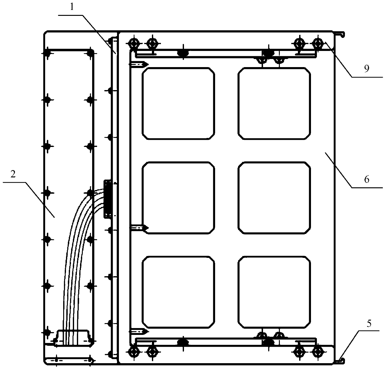
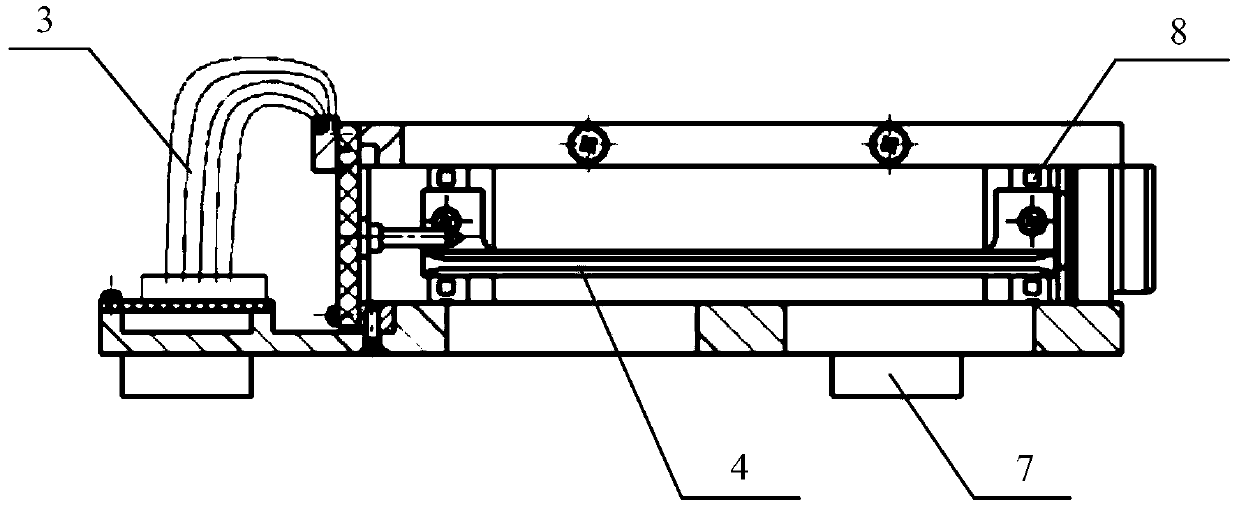
[0011] 1. The VPX module interface board is designed and installed on the interface socket and micro-rectangular socket adapted to the VPX module to be tested. The power and control signals are sent to the micro-rectangular socket. The VPX module interface board is installed vertically at the rear of the horizontal VPX module mounting frame. ;

[0012] 2. The power supply and control adapter board are designed and installed with voltage stabilizing circuit, dial switch circuit, light-emitting diode circuit and micro-rectangular socket. The power supply and control signal are sent to the micro-rectangular socket, and the power supply and control adapter board are installed horizontally. On the bottom plate of the VPX module mounting frame;

[0013] 3. The VPX module interface board and the power supply and control adapter board are interconnected through the micro rectangular socket connection cable;

[0014] 4. A pair of guide rails and upper and lower cross beams are installed on t...


PUM


Abstract

The invention relates to a horizontal type VPX module debugging device comprising a horizontal type VPX module mounting rack, a VPX module interface board power supply and control adapter board and aconnecting cable, wherein the horizontal type VPX module mounting rack comprises bottom plate and an open type top plate, four cushion blocks are installed below the bottom plate and used for supporting the bottom plate, a pair of guide rails, an upper cross beam and a lower cross beam are installed between the bottom plate and the open type top plate, the guide rail is used for guiding insertionand extraction of the VPX module and fixing an upper guide pin and a lower guide pin thereof, and the upper and lower cross beams and built-in nut strips are used for mounting and fixation of the guide rails and locking and starting of an upper handle and a lower handle of the VPX module; the VPX module interface board is vertically mounted on the rear portion of the horizontal type VPX module mounting rack; and the power supply and control adapter board is horizontally mounted on the bottom plate of the horizontal type VPX module mounting rack. According to the horizontal type VPX module debugging device in the invention, horizontal placement of the VPX module is realized, one-time insertion and extraction is only required for one-time debugging, operations such as index tuning, fault removal, component replacement and the like during debugging are facilitated, and the mechanical service life of the VPX interface is guaranteed.

Description

Technical field [0001] The invention relates to the technical field of a debugging device. Background technique [0002] The VPX bus is a new generation of high-speed serial bus standard proposed by the VITA organization in 2007 on the basis of the VME bus. VPX standard boards based on VITA specifications have been widely used in military, industrial control and other fields. The structure of VPX plug and socket is composed of dozens of reed inserts and interface modules such as optical fiber and radio frequency. It is characterized by high integration, low transmission loss and strong reliability. [0003] Based on the above structural characteristics of the VPX interface, the VPX module designed by the engineer needs to be debugged using a special debugging R&D platform. At present, the conventional debugging R&D platform is mainly composed of VPX adapter board and VPX debugging chassis. Its characteristic is that the VPX module to be adjusted is directly inserted into the chas...

Claims


Application Information

Patent Timeline
Patent Type & Authority Applications(China)
IPC IPC(8): G01R31/00G01R1/20H01R13/631
CPCG01R1/20G01R31/00H01R13/631
Inventor 祁全朱曾辉吴梅陈建囡
Owner THE 724TH RES INST OF CHINA SHIPBUILDING IND
Learn More