An electronic component and casing method and device thereof

A technology for electronic components and casing equipment, applied in sorting, metal processing and other directions, can solve the problems of low clamping accuracy, low production efficiency, affecting quality, etc., to facilitate subsequent grasping, high equipment success rate, and improved linearity degree of effect

Active Publication Date: 2021-06-22
杭州众道光电科技有限公司
View PDF2 Cites 0 Cited by
  • Summary
  • Abstract
  • Description
  • Claims
  • Application Information

AI Technical Summary

Problems solved by technology

[0002] Electronic components are prone to short circuits after they are packaged on the circuit board
In order to solve the problem of short circuits between electronic components, the existing common method is to set sleeves on the electronic components. Since most of the electronic components are small in size, it is very inconvenient to operate and the production efficiency is low. Generally, rubber hose equipment is used for casing. Operation, the steps are divided into feeding, casing, heat shrinking and forming. For example: China State Intellectual Property Office published a publication number of CN205148896U on April 13, 2016, and the patent name is a patent for a fully automatic casing forming machine. The patent includes Machine, the machine is equipped with component conveying mechanism, casing conveying mechanism, casing threading mechanism, heat shrinking mechanism and forming mechanism, casing conveying mechanism is installed between the component conveying mechanism and casing threading mechanism, The tube mechanism is installed between the casing conveying mechanism and the heat shrinking mechanism, and the heat shrinking mechanism is installed between the casing threading mechanism and the forming mechanism. Mechanism, the clip conveyor is slidingly connected to the machine table
The patented electronic components do not have a straightening process, and the yield rate of the product is low
[0003] The feeding of the existing technology is mostly by the vibration of the turntable, and the electronic components are easy to block the guide column in the silo and get stuck, which will also deform the electronic components and affect the quality; the casing threading mechanism directly clamps the rubber hose, and the length of the rubber hose needs to be advanced The cutting is good, it is not easy to adjust in real time, and the positioning accuracy before clamping is required to be high
To sum up, the existing tube-in-tube rubber hose equipment has the following shortcomings: 1. Electronic components are not loaded stably, and they are easy to cross-wind; 2. The rubber hose is cut in advance, the adaptability of the equipment is not high, and the clamping accuracy is low; 3. The straightness of electronic components is low, there is no adhesive tape mechanism, and the product qualification rate is low

Method used


Image

  • An electronic component and casing method and device thereof
  • An electronic component and casing method and device thereof
  • An electronic component and casing method and device thereof

Examples


Embodiment Construction

[0032] The following will clearly and completely describe the technical solutions in the embodiments of the present invention with reference to the accompanying drawings in the embodiments of the present invention. Obviously, the described embodiments are only some, not all, embodiments of the present invention.

[0033] In describing the present invention, it should be understood that the terms "upper", "lower", "front", "rear", "left", "right", "top", "bottom", "inner", " The orientation or positional relationship indicated by "outside" and other indications are based on the orientation or positional relationship in the drawings, and are only for the convenience of describing the present invention and simplifying the description, rather than indicating or implying that the device or element referred to must have a specific orientation, use a specific orientation construction and operation, therefore, should not be construed as limiting the invention.

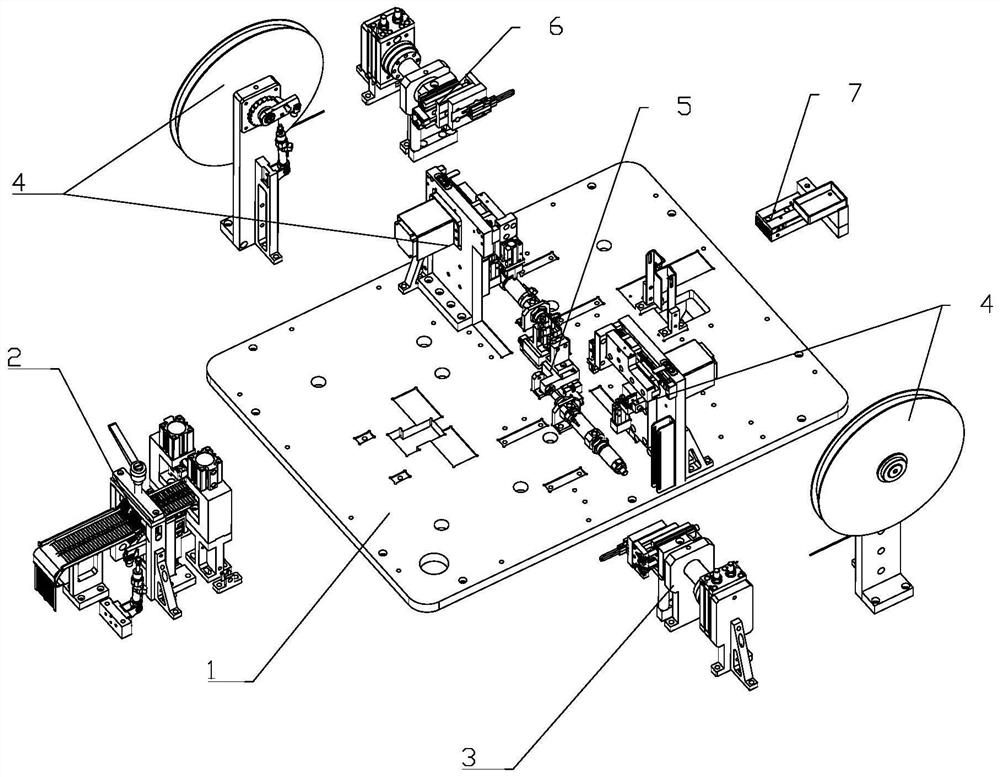
[0034] like figure 1 ...


PUM


Abstract

The invention relates to the technical field of electronic component production equipment. An electronic component bushing device, comprising an electronic component shaping and feeding device on a frame, a first removing device, a hose cutting and feeding device, a positioning device, a second removing device and a sorting device; the positioning device is fixed In the middle of the frame, the electronic component shaping and feeding device is connected with the positioning device through the first removal device, the second removal device is connected with the discharge end of the positioning device, and the sorting device is connected with the second removal device. The rubber hose cutting and feeding device is provided with two groups of left and right, which correspond to the positioning device and are located on both sides of the positioning device. The advantages of this patent are that the terminals of the electronic components are straightened, and the rate of good products is high; the feeding of the electronic components is stable, the electronic components do not interfere with each other, and the success rate of the equipment is high; the length of the rubber hose can be adjusted, and the broken material can be detected.

Description

technical field [0001] The invention relates to the technical field of electronic component production. Background technique [0002] Electronic components are prone to short circuits after they are packaged on circuit boards. In order to solve the problem of short circuits between electronic components, the existing common method is to set sleeves on the electronic components. Since most of the electronic components are small in size, it is very inconvenient to operate and the production efficiency is low. Generally, rubber hose equipment is used for casing. Operation, the steps are divided into feeding, casing, heat shrinking and forming. For example: China State Intellectual Property Office published a publication number of CN205148896U on April 13, 2016, and the patent name is a patent for a fully automatic casing forming machine. The patent includes Machine, the machine is equipped with component conveying mechanism, casing conveying mechanism, casing threading mechani...

Claims


Application Information

Patent Timeline
Patent Type & Authority Patents(China)
IPC IPC(8): B29C63/42B26D1/08B26D7/06B21F11/00B21F1/00B21F1/02B21F23/00B07C5/00B07C5/38
CPCB07C5/00B07C5/38B21F1/00B21F1/026B21F11/00B21F23/00B26D1/08B26D7/06B29C63/0004B29C63/42
Inventor 陆阳清王凯陈泽楷张鑫洋
Owner 杭州众道光电科技有限公司
Why Eureka
Try Eureka