
Machining machine tool for spiral bevel gears

A technology for spiral bevel gears and machine tools, which is applied to gear cutting machines, metal processing equipment, gear tooth manufacturing devices, etc., can solve the problems of complex overall structure and complicated adjustment of machine tools, achieve simple overall structure, realize synchronous processing, and reduce quantity Effect

Pending Publication Date: 2019-11-08
HENAN UNIV OF SCI & TECH
View PDF1 Cites 1 Cited by
  • Summary
  • Abstract
  • Description
  • Claims
  • Application Information

AI Technical Summary

Problems solved by technology

[0004] The purpose of the present invention is to provide a spiral bevel gear processing machine tool to solve the technical problem that the existing double-station machine tool is equipped with a transmission mechanism for synchronous adjustment of two workpiece boxes and two tool boxes, which leads to complex overall structure of the machine tool and cumbersome adjustments

Method used


Image

  • Machining machine tool for spiral bevel gears
  • Machining machine tool for spiral bevel gears
  • Machining machine tool for spiral bevel gears

Examples


Embodiment 1

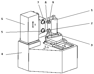
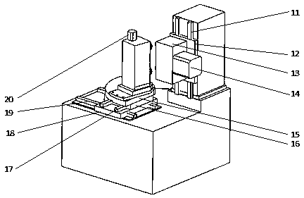
[0034] The spiral bevel gear processing machine tool in Embodiment 1 can process two spiral bevel gears at the same time, at this time, M=N=2.

[0035] like Figure 1-4 As shown, the spiral bevel gear processing machine tool includes a workpiece box 1 and a tool box 13, and the two are used together to realize the machining of the spiral bevel gear. The machine tool can be a gear milling machine or a gear grinding machine, and different types of Machined cutterhead.

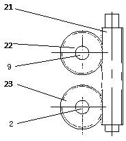
[0036] Specifically, in the workpiece box 1, there are two workpiece spindles arranged in parallel and extending in parallel to install the workpiece. The workpiece is a spiral bevel gear, and the axes of the two workpiece spindles are parallel to each other. A workpiece motor 20, the workpiece motor 20 drives two workpiece spindles to rotate synchronously through a worm gear transmission mechanism.

[0037] The worm and worm gear mechanism includes a worm 21, a first worm 23 and a second worm 22. The workpiece m...

Embodiment 2

[0045] The spiral bevel gear processing machine tool in Embodiment 2 can process three spiral bevel gears at the same time, at this time, M=N=3. In the spiral bevel gear processing machine tool in Embodiment 2, only the structures of the workpiece box and the tool box are different from those in Embodiment 1, and the other structures of the machine tool are the same.

[0046] like Figure 5-6 As shown, the tool box is provided with three tool spindles arranged in parallel extending in parallel for installing machining tools. The axes of the three tool spindles are parallel to each other. A tool motor 14 is fixed on the tool box 13. The tool The motor drives the three tool spindles to rotate synchronously through the synchronous belt transmission mechanism.

[0047] The synchronous belt transmission mechanism comprises the driving pulley 28 that is connected with the cutter motor 14 transmission, and the first driven pulley 30, the second driven pulley 31, the 3rd driven belt ...


PUM


Abstract

The invention provides a machining machine tool for spiral bevel gears. The machining machine tool comprises a workpiece box and a tool box. M workpiece spindles which stretch in parallel and are usedfor mounting workpieces are sequentially arranged and integrated in the workpiece box, a workpiece motor is fixedly arranged on the workpiece box, and the workpiece motor drives the M workpiece spindles to synchronously rotate through a workpiece synchronous transmission mechanism. N tool spindles which stretch in parallel and are used for mounting machining tools are sequentially arranged and integrated in the tool box, a tool motor is fixedly arranged on the tool box, and the tool motor drives the N tool spindles to synchronously rotate through a tool synchronous transmission mechanism. M is equal to N, and N is 2 or 3. The sequential distribution direction of the M tool spindles is equal to that of the N workpiece spindles, the adjacent intervals of the M tool spindles are equal to those of the N workpiece spindles, thus, the M tool spindles correspond to the N workpiece spindles one to one, and then the M spiral bevel gears are simultaneously machined.

Description

technical field [0001] The invention relates to a spiral bevel gear processing machine tool. Background technique [0002] Spiral bevel gear is a relatively complex gear in gears. Spiral bevel gear can be divided into two types: circular arc reduction gear and cycloidal contour bevel gear. The processing equipment currently used mainly includes mechanical and numerical control processing machine tools. These two types of processing machine tools are all on one machine tool, using one tool to process the large or small wheel of the spiral bevel gear. In the prior art, a spiral bevel gear double-station gear milling machine disclosed in the Chinese invention patent whose authorized notification number is CN107175372B, the two X-direction sliding tables on the machine tool are located at the horizontal two sides of the Y-direction sliding table in the middle. On the side, each X-direction sliding table is equipped with a turntable, and the two turntables are equipped with two ...

Claims


Application Information

Patent Timeline
IPC IPC(8): B23F9/00B23F23/00B23F23/02
CPCB23F9/00B23F23/006B23F23/02
Inventor 张华杨建军翟向毅李聚波聂少武
Owner HENAN UNIV OF SCI & TECH
Learn More