Steel core aluminum stranded wire aluminum embedded tensile wire clamp structure

A technology of steel-cored aluminum stranded wire and tension clamp, applied in the direction of adjusting/maintaining mechanical tension, etc., can solve the problems of biting the steel wire of the steel stranded wire, insufficient crimping pressure, gaps in the aluminum stranded wire, etc., so as to reduce the labor intensity , The effect of reducing engineering costs and high crimping quality

Pending Publication Date: 2019-11-05
GUIZHOU POWER GRID CO LTD
View PDF0 Cites 2 Cited by
  • Summary
  • Abstract
  • Description
  • Claims
  • Application Information

AI Technical Summary

Problems solved by technology

[0004] In the traditional crimping process of tension clamps for overhead conductors in power transmission and transformation projects, the joints of galvanized steel strands (or aluminum-clad steel strands) of steel-cored aluminum strands are directly covered with steel strands by steel anchor crimping tubes. Line hydraulic connection, if the hardness of the steel anchor crimping tube and the steel strand does not match, the size of the crimping die is unreasonable, and the crimping pressure is insufficient, defects such as underpressure, loose strands, overpressure, and steel wire surface damage are prone to occur, resulting in joint grip Efforts not to meet standard requirements
Among the factors that cause steel strand crimping defects of steel cored aluminum stranded wire, the hardness mismatch between steel anchor crimping tube and steel strand is the most unavoidable. In the production process of aluminum clad steel strand, cold drawn steel wire passes through Liquid aluminum plating is equivalent to tempering once, and the hardness of the cold-drawn steel wire is reduced, resulting in a lower hardness of the steel strand than the steel anchor crimping tube. Focus on lowering
[0005] (2) It is difficult to guarantee the crimping quality of the aluminum sleeve clamp
[0008] In winter, when the temperature drops, because the steel core is in the elastic range, the cross section of the steel core becomes thinner, the pressure applied by the steel core to the aluminum strand decreases, and the cross section of the aluminum strand also shrinks, but because the aluminum strand has already undergone yield hardening, The cross-section of the aluminum strands did not expand due to the reduction in pressure, which resulted in gaps between the aluminum strands
[0009] Rainwater, air, dirt, and corrosive media infiltrate the gap between the aluminum strands of the joint, oxidize the surface of the aluminum strands, and generate aluminum oxide, which leads to increased contact resistance and heat generation at the crimping joints of the steel-reinforced aluminum strands. , eventually failing

Method used


Image

  • Steel core aluminum stranded wire aluminum embedded tensile wire clamp structure
  • Steel core aluminum stranded wire aluminum embedded tensile wire clamp structure
  • Steel core aluminum stranded wire aluminum embedded tensile wire clamp structure

Examples


Embodiment 1

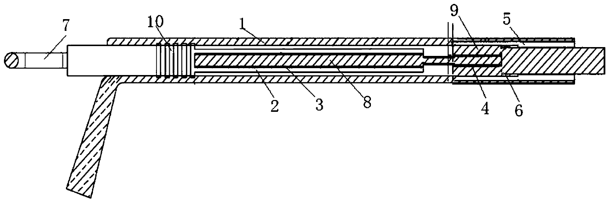
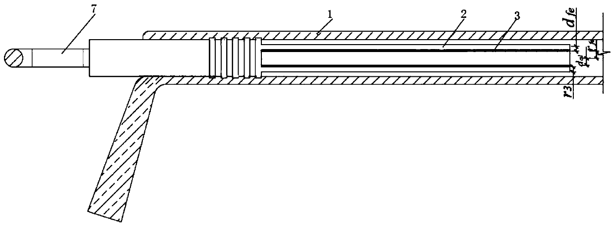
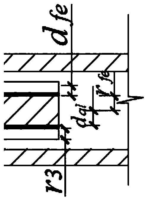
[0022] Embodiment 1: as Figure 1-5 As shown, a steel-cored aluminum stranded wire embedded aluminum tension clamp structure, including casing clamp 1, steel anchor crimping tube 2, steel core embedded aluminum tube 3, inner embedded layer aluminum tube 4, outer embedded layer aluminum tube 5 , wire shaping ring 6 and clamp anchor ring 7, steel core embedded aluminum tube 3 is sleeved on steel strand 8 at the crimping end of steel cored aluminum stranded wire, and steel anchor crimping tube 2 is sleeved outside steel core embedded aluminum tube 3 , crimping the steel anchor crimping tube 2 so that the steel core embedded aluminum tube 3 closely fits the steel strand 3 to form a steel strand crimping joint; the inner layer aluminum tube 4 is placed on the steel strand of the steel core aluminum strand at the crimping end Between the wire 7 and the inner aluminum stranded wire layer 9, the steel cored aluminum stranded wire at the crimping end is connected with the outer embedde...

Embodiment 2

[0026] Embodiment 2: A full-tension aluminum-embedded crimping method for aluminum-steel-cored stranded wires, the steps of which are as follows:

[0027] 1) Cut off the aluminum stranded wire at the crimping end of the steel-cored aluminum stranded wire to expose the steel core, the length of the cut-off section = the length of the steel anchor crimping tube + 20mm;

[0028] 2) Pull the crimping end of the steel-cored aluminum stranded wire with the set length of the aluminum stranded wire to 10 meters, insert the aluminum sleeve clamp 1 from the end of the steel-cored aluminum stranded wire, and move the aluminum sleeve clamp 1 to the Does not affect the position of the next process;

[0029] 3) Insert the steel-cored aluminum stranded wire into the outer embedded aluminum tube 5, and press the large inner diameter end of the outer embedded aluminum tube 5 towards the joint, and move the outer embedded aluminum tube to a position that does not affect the next process;

[00...


PUM


Abstract

The invention discloses a steel core aluminum stranded wire aluminum embedded tensile wire clamp structure which comprises a casing wire clamp, a steel anchor crimped pipe, a steel core aluminum embedded pipe, an internal embedded layer aluminum pipe, an external embedded layer aluminum pipe and a wire shaping ring. The steel core aluminum embedded pipe is placed between a steel stranded wire of asteel core aluminum stranded wire crimping end and the steel anchor crimping pipe. The internal embedded layer aluminum pipe is placed between a steel stranded wire of a crimping end steel core aluminum stranded wire and an internal aluminum stranded wire layer, the crimping end steel core aluminum stranded wire is sleeved in the external embedded layer aluminum pipe, and the a sleeve hole of thecasing wire clamp sleeves the external embedded layer aluminum pipe on the steel core aluminum stranded wire and the steel anchor crimped pipe. According to the invention, the crushing damage, underpressure and loose strand of the steel core aluminum stranded wire are avoided, the manufacture is easy, the crimping quality is high, the non-destructive detection is avoided, and the labor intensityand engineering cost are reduced.

Description

technical field [0001] The invention belongs to the technical field of steel-core aluminum stranded wire embedded aluminum tension clamps, and in particular relates to a steel core aluminum stranded wire embedded aluminum tension clamp structure. Background technique [0002] The existing steel-cored aluminum stranded wire strain clamp is mainly composed of a steel anchor crimping tube and an aluminum crimping tube. When crimping, first peel off a section of the aluminum stranded wire to expose the steel strand, and use the steel anchor crimping tube to crimp the steel strand. , and then use the aluminum alloy crimping tube to crimp the aluminum alloy connecting tube, aluminum strand, and steel strand together. This traditional crimping method is prone to two problems: [0003] (1) Damage to the steel core caused by the crimping of the steel anchor crimping tube [0004] In the traditional crimping process of tension clamps for overhead conductors in power transmission and...

Claims


Application Information

Patent Timeline
IPC IPC(8): H02G7/02
CPCH02G7/02
Inventor 张仁奇张义钊
Owner GUIZHOU POWER GRID CO LTD
Why Eureka
Try Eureka