


Quick Research
Generate reliable direction feasibility study reports for your R&D in just a few steps.

Technical Q&A
Discover and master advanced knowledge NOW. Basics, ideas, possibilities, all at once.

Find Solutions
As an expert in R&D theories, this can generate solutions to your technical problems instantly.

Evaluate Feasibility
Analyze your overall solution with one click, know your potential R&D risks in advance.

Monitor Landscape
Get weekly tech updates, stay abreast of the latest tech innovations and key insights.
Vibration suppressing structure
A vibration damping structure and component technology, applied in the direction of friction damper, non-rotational vibration suppression, etc., can solve the problems of inability to obtain sufficient vibration damping effect, limit the length and thickness of linear components, etc., to increase bending moment, suppress Effects of vibration and increased friction
- Summary
- Abstract
- Description
- Claims
- Application Information
AI Technical Summary
Problems solved by technology
Method used
Image

Examples
no. 1 example
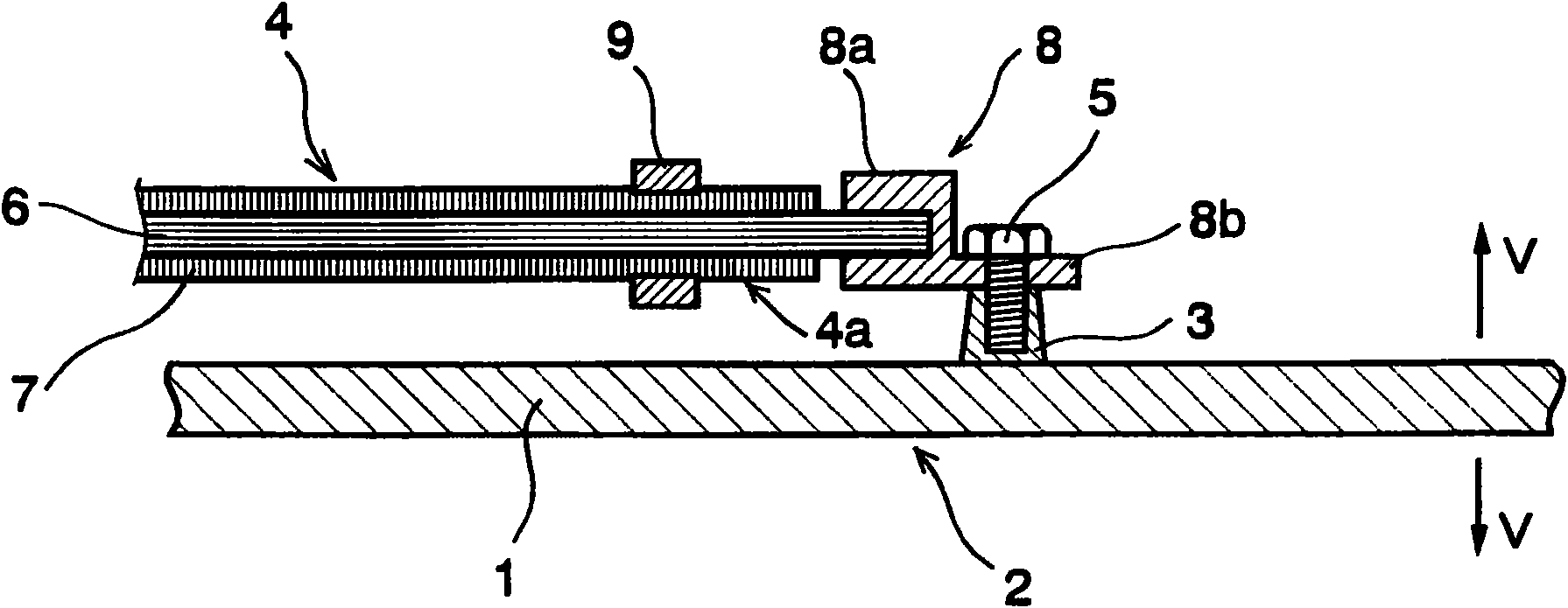
[0032] The present invention will be described based on specific examples. figure 1 It is a schematic diagram for explaining the first embodiment of the vibration damping structure in the present invention, and here is an example of a structure in which, for example, a transmission 1 mounted on a vehicle is used as the vibration damping object 1 .
[0033] exist figure 1 , in the direction mainly indicated by the arrow V ( figure 1 On the vibration-damping site 2 of the vibration-damping object 1 that vibrates in the vertical direction), there is provided a boss portion 3 integrally formed with or fixed to the vibration-damping object 1 . The boss portion 3 is integrally formed by, for example, casting, or fixed by welding or bonding, and is integrated with the vibration-damping object 1 , that is, the vibration-damping site 2 of the transmission case 1 .
[0034] The linear member 4 is integrally fixed to the boss portion 3 of the transmission case 1 by bolting, for example...
no. 2 example
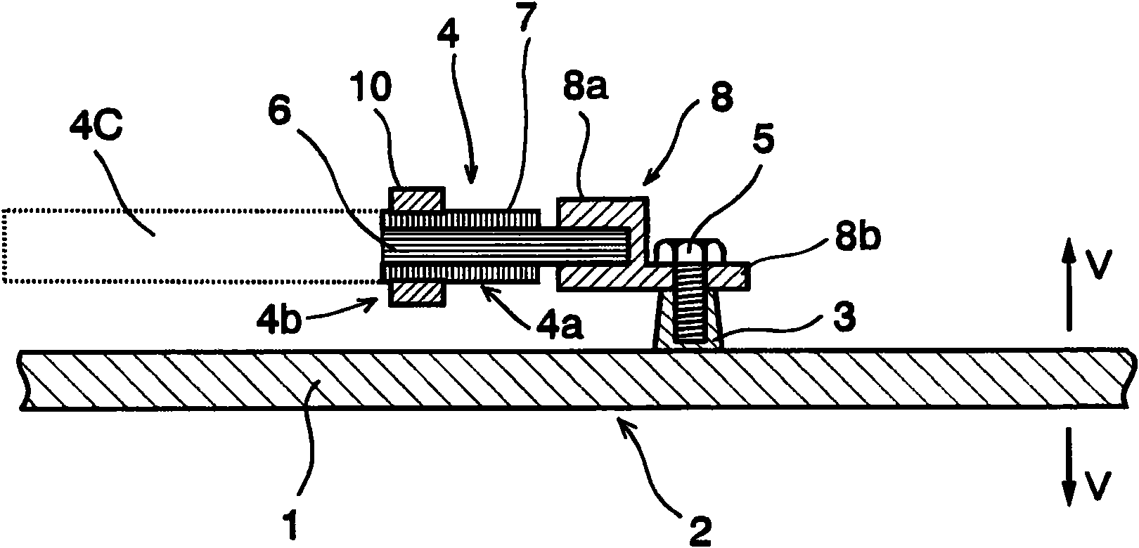
[0045] figure 2 It is a schematic diagram for explaining the second embodiment of the vibration damping structure of the present invention, showing the above-mentioned figure 1 This is an example of a partially modified configuration of the structure of the first embodiment shown. Therefore, for figure 1 The constituent parts identical to those in the first embodiment shown are marked with figure 1 The same reference symbols are used, and detailed descriptions thereof are omitted.
[0046] exist figure 2 Among them, the side of the linear part 4 that is not fixed with the mounting part 8 ( figure 2 The left side in the figure), that is, the end portion 4b on the free end side of the linear member 4 is fitted with a crimping member 10 . The crimping member 10 may have the same configuration as the above-mentioned crimping member 9 and the main body portion 8a of the mounting member 8, and is formed so that the other end of the linear member 4, that is, the rear end ( ...
no. 3 example
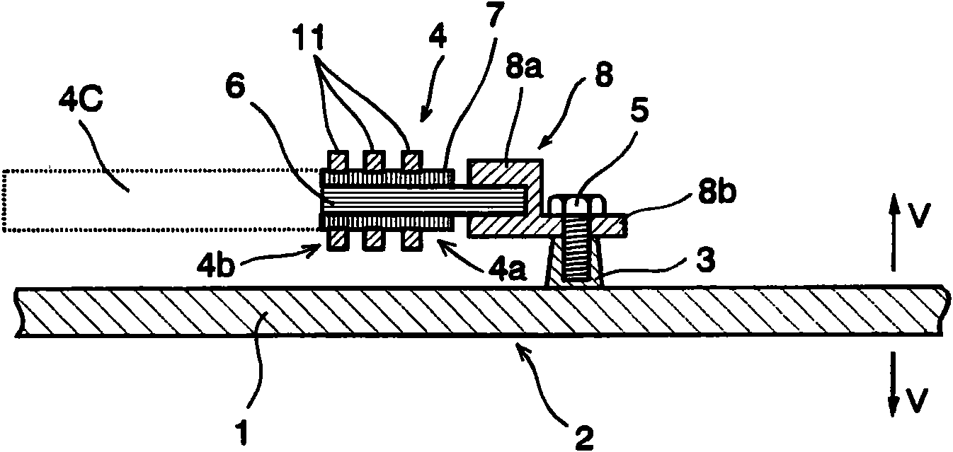
[0056] image 3 It is a schematic diagram for explaining the third embodiment of the vibration damping structure of the present invention, which shows the above-mentioned figure 2 A modification of the configuration of the second embodiment shown. Therefore, for figure 2 In the shown second embodiment, the same constituent parts are marked with figure 2 The same reference numerals are used, and detailed descriptions thereof are omitted.
[0057] exist image 3 In, the side of the linear part 4 to which the mounting part 8 is not fixed ( image 3 On the left side in the middle), that is, on the end 4b of the free end side of the linear member 4, the crimping member 11 is attached. This crimping member 11 is divided into a plurality, and they respectively have the same configuration as the above-mentioned crimping members 9 and 10 and the main body portion 8a of the attachment member 8 . And, it is formed so that the other top end of the linear member 4, that is, the re...
PUM
 Abstract
Description
Claims
Application Information
 - R&D Engineer
- R&D Manager
- IP Professional
- Industry Leading Data Capabilities
- Powerful AI technology
- Patent DNA Extraction
Browse by: Latest US Patents, China's latest patents, Technical Efficacy Thesaurus, Application Domain, Technology Topic, Popular Technical Reports.
© 2024 PatSnap. All rights reserved.Legal|Privacy policy|Modern Slavery Act Transparency Statement|Sitemap|About US| Contact US: help@patsnap.com