
Display panel back plate structure and preparation method thereof, and top emission type display panel

A display panel and backplane technology, applied in electrical components, electrical solid-state devices, circuits, etc., can solve problems such as poor surface flatness of pixel electrodes, uneven light emission of top-emitting OLEDs, etc.

Inactive Publication Date: 2019-11-05
GUANGDONG JUHUA PRINTING DISPLAY TECH CO LTD
View PDF7 Cites 7 Cited by
  • Summary
  • Abstract
  • Description
  • Claims
  • Application Information

AI Technical Summary

Problems solved by technology

The pixel electrode of the top-emitting display panel covers the driving circuit, and the driving circuit is difficult to planarize in the pre-production process, so the flatness of the pixel electrode surface is poor, resulting in uneven light emission of the top-emitting OLED.

Method used


Image

  • Display panel back plate structure and preparation method thereof, and top emission type display panel
  • Display panel back plate structure and preparation method thereof, and top emission type display panel
  • Display panel back plate structure and preparation method thereof, and top emission type display panel

Examples


Embodiment Construction

[0055] In order to facilitate the understanding of the present invention, a more comprehensive description of the present invention will be given below, and preferred embodiments of the present invention will be given. However, the present invention can be implemented in many different forms and is not limited to the embodiments described herein. On the contrary, the purpose of providing these embodiments is to make the understanding of the disclosure of the present invention more thorough and comprehensive.

[0056] Unless otherwise defined, all technical and scientific terms used herein have the same meaning as commonly understood by those skilled in the technical field of the present invention. The terms used in the description of the present invention herein are only for the purpose of describing specific embodiments, and are not intended to limit the present invention. The term "and / or" as used herein includes any and all combinations of one or more related listed items.

[...


PUM


Abstract

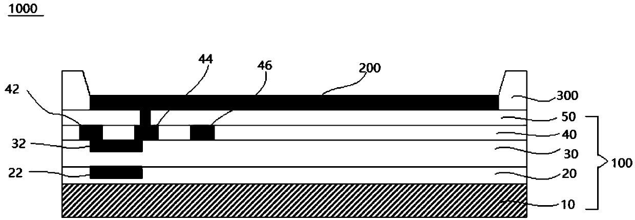
The invention relates to a top emission type display panel; the top emission type display panel comprises a substrate, a buffer layer, a grid electrode, an insulating layer, an active layer, a protective layer, a source electrode, a drain electrode, an auxiliary electrode, a flat layer, a pixel electrode and a pixel definition layer. According to the top emission type display panel, the grid electrode is embedded in the buffer layer and forms a flat surface with the buffer layer; the active layer is embedded in the insulating layer and forms a flat surface with the insulating layer; the sourceelectrode, the drain electrode and the auxiliary electrode are embedded in the protective layer and form a flat surface with the protective layer, so that a flat surface is formed on the surface of the whole substrate after a TFT driving circuit is manufactured, the problem that the surface of the pixel electrode is uneven due to the driving circuit of the top emission type display panel is avoided, the luminous uniformity of the top emission display panel is effectively improved, and the display effect is improved.

Description

Technical field [0001] The invention relates to the technical field of organic light-emitting electronic devices, and in particular to a display panel backplane structure, a preparation method thereof, and a top emission display panel. Background technique [0002] Organic electroluminescent diodes (OLEDs) have become one of the main directions of current display research due to their self-luminous, fast response, wide viewing angle, high brightness, lightness and thinness. OLED displays are mainly manufactured by solution processing, which has the advantages of low cost, high productivity, and easy realization of large sizes, and has become an important direction for future display technology development. Among them, printing technology is considered to be the most effective way to realize OLED low-cost and large-area full-color display. [0003] Since the OLED display panel needs to use a more complicated driving circuit for compensation, a large part of its TFT backplane is cov...

Claims


Application Information

Patent Timeline
IPC IPC(8): H01L27/32H01L27/12
CPCH01L27/1214H01L27/1259H10K59/12
Inventor 史文陈亚文
Owner GUANGDONG JUHUA PRINTING DISPLAY TECH CO LTD
Learn More