
Roof-distributed multi-air-port synergistic individualized air supply method and air supply system

A distributed and multi-vent technology, which is applied in heating and ventilation control systems, heating and ventilation safety systems, and pipeline layout, etc., can solve the problem of restricting positioning air supply, difficult to change control areas, and lack of individual differences in air conditioning systems, etc. problems, achieve high thermal comfort and save energy

Active Publication Date: 2019-11-05
SHANGHAI JIAO TONG UNIV
View PDF12 Cites 10 Cited by
  • Summary
  • Abstract
  • Description
  • Claims
  • Application Information

AI Technical Summary

Problems solved by technology

[0005] To sum up, the existing air-conditioning system lacks the distinction of individual differences, and generally needs to regulate the thermal environment of the entire room through high-power output to act on users, and the correspondingly designed station air-conditioning system has the limitation that the control area is not easy to change sex
At the same time, the above-mentioned existing patents all start from the overall system operation method, and the way of horizontal air supply limits the role of positioning air supply

Method used


Image

  • Roof-distributed multi-air-port synergistic individualized air supply method and air supply system
  • Roof-distributed multi-air-port synergistic individualized air supply method and air supply system
  • Roof-distributed multi-air-port synergistic individualized air supply method and air supply system

Examples


Embodiment Construction

[0041] The following describes several preferred embodiments of the present invention with reference to the accompanying drawings, so as to make the technical content clearer and easier to understand. The present invention can be embodied in many different forms of embodiments, and the protection scope of the present invention is not limited to the embodiments mentioned herein.

[0042] In the drawings, components with the same structure are denoted by the same numerals, and components with similar structures or functions are denoted by similar numerals. The size and thickness of each component shown in the drawings are shown arbitrarily, and the present invention does not limit the size and thickness of each component. In order to make the illustration clearer, the thickness of parts is appropriately exaggerated in some places in the drawings.

[0043] The present invention firstly provides a method and an air supply system for collaborative individualized air supply with di...


PUM


Abstract

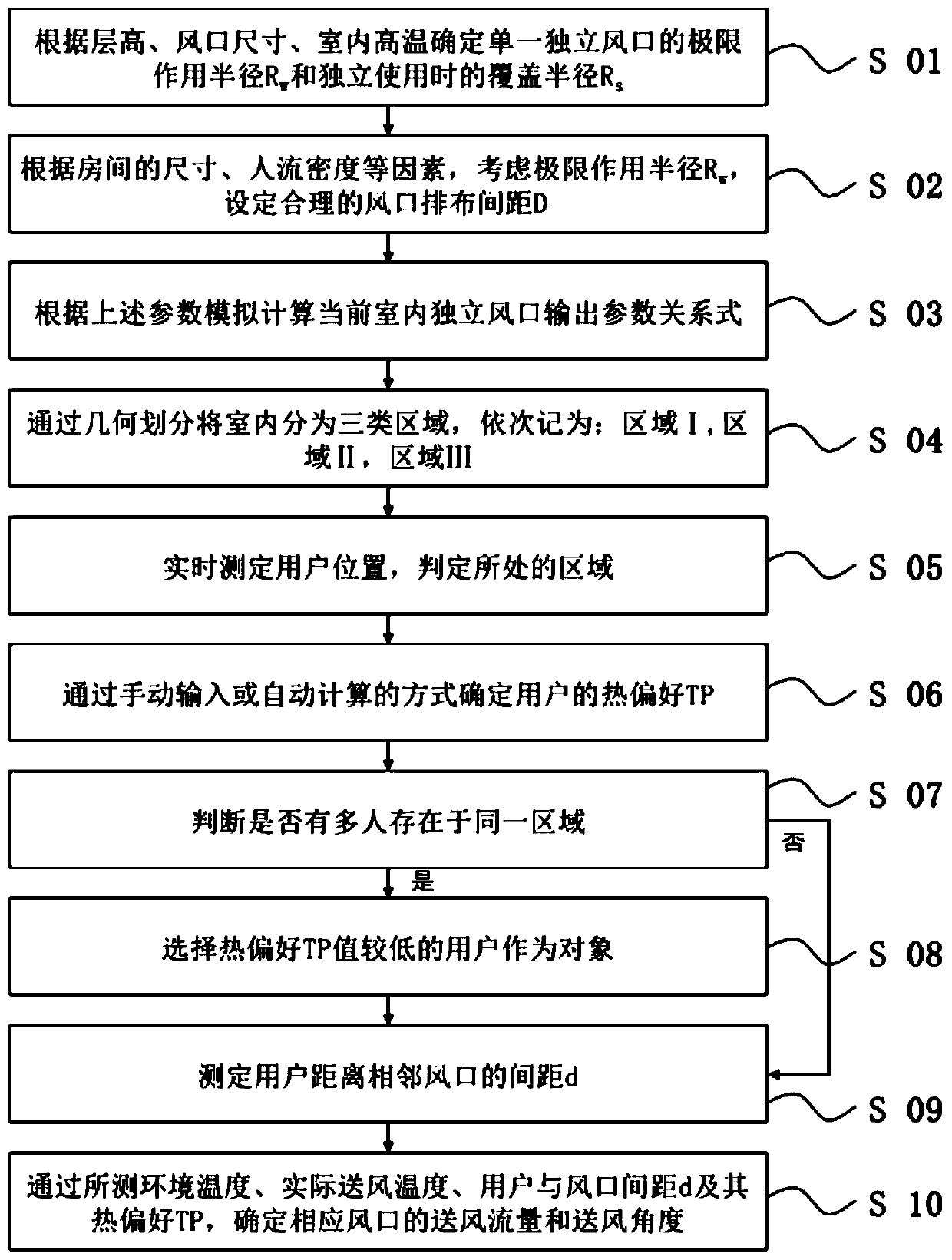
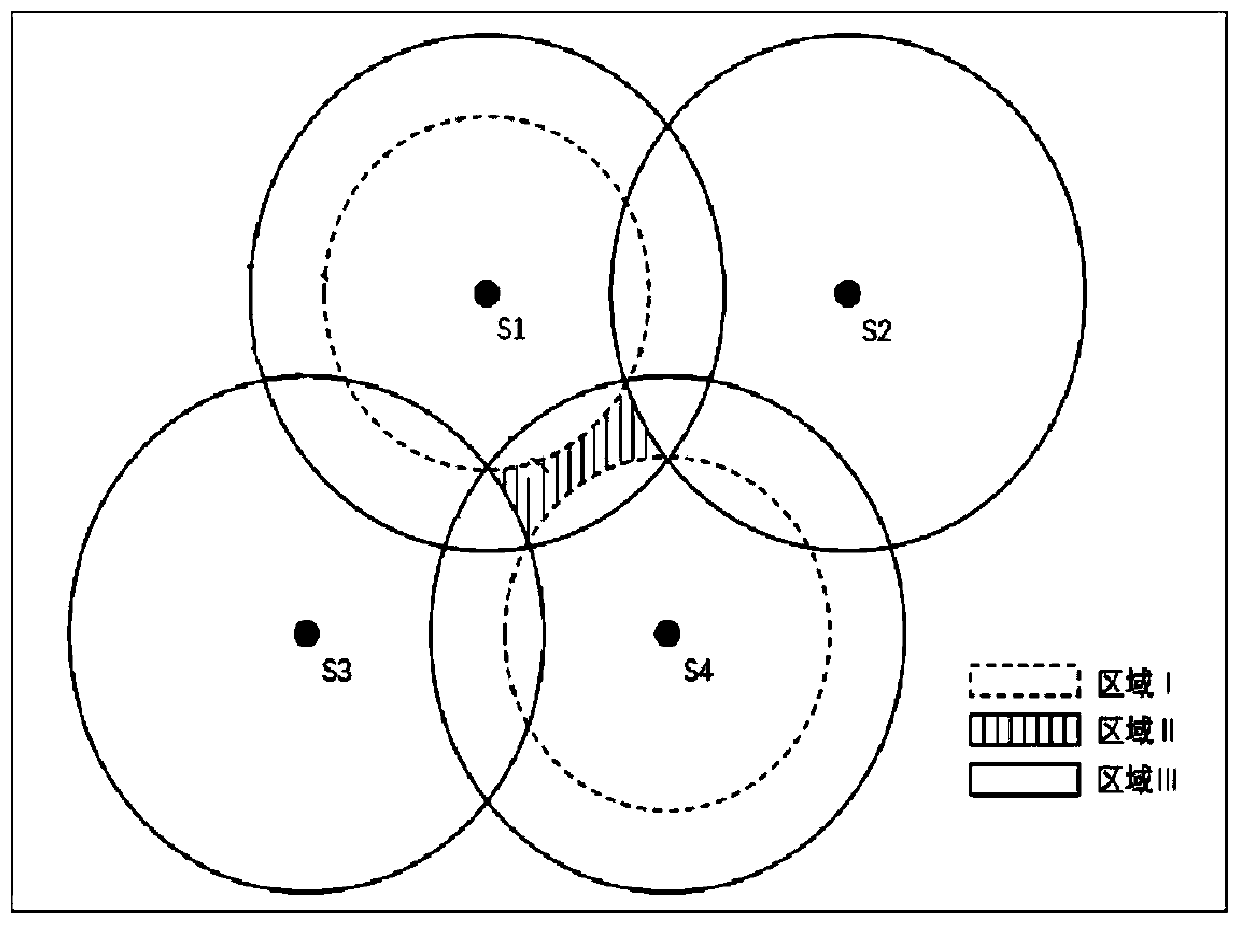
The invention relates to the technical field of air conditioning, and discloses a roof-distributed multi-air-port synergistic individualized air supply method and an air supply system. The air supplymethod comprises the following steps of determining an extremity action radius Rw of a single independent air port and a coverage radius Rs during independent use; setting the layout of air ports; fitting a relation between air supply parameters of the air ports, the indoor environment temperature, actual air supply parameters, the distances d between users and the air ports and thermal preferences TP of the users according to multiple example results simulated by CFD; dividing the interior of a room into three kinds of areas; measuring positions of the users and partition types to which the users belong; determining the thermal preferences TP of the users; judging whether or not multiple users exist in each area, and if yes, regarding the users with low TP values as objects; determining the distances d between the users and the acting air ports; determining the air supply flow and air supply angle of each air port, implementing the decision through a control system, and conducting comfortable air supply meeting the individualized thermal preference requirements of the users. By means of the roof-distributed multi-air-port synergistic individualized air supply method and the air supply system, a comfortable environment is quickly provided, and the energy is saved.

Description

technical field [0001] The invention relates to the technical field of air conditioning, and in particular to a roof distributed multi-tuyere cooperative individualized air supply method and an air supply system. Background technique [0002] In recent years, the air-conditioning air supply method based on the thermal comfort of the human body has gradually become a new development direction of the air-conditioning system. Most of the existing air-conditioning systems pursue universality, and mostly take the average value of the demand feedback of the general public as the regulation target, while ignoring the large differences in heat preferences among individuals. Therefore, in order to achieve the ultimate goal of personalized air conditioning regulation, it is very important to effectively monitor the user's physiological parameters related to thermal sensation and accurately determine the degree of individual thermal preference. [0003] On the other hand, because the ...

Claims


Application Information

Patent Timeline
Patent Type & Authority Applications(China)
IPC IPC(8): F24F13/06F24F11/74F24F11/79F24F11/46F24F120/12
CPCF24F13/06F24F11/46F24F11/74F24F11/79F24F2120/12
Inventor 张爱丽胡嘉文单橙橙吴建宏丁国良徐学敏
Owner SHANGHAI JIAO TONG UNIV
Learn More