An air purification system with dredging function using photocatalyst technology
What is Al technical title?
Al technical title is built by PatSnap Al team. It summarizes the technical point description of the patent document.
An air purification system and photocatalyst technology, applied in air conditioning systems, household appliances, applications, etc., can solve problems such as poor air circulation, difficult disassembly and assembly, and reduced air purification efficiency, so as to improve the effect, improve practicability, and ensure dredging Effect
Active Publication Date: 2021-04-16
山东摩卡智能科技有限公司
View PDF8 Cites 0 Cited by
Summary
Abstract
Description
Claims
Application Information
AI Technical Summary
This helps you quickly interpret patents by identifying the three key elements:
Problems solved by technology
Method used
Benefits of technology
Problems solved by technology
[0003] When the existing photocatalyst air purifiers are in use, they need to cooperate with ultraviolet lamps to irradiate ultraviolet rays on the surface of the photocatalyst to produce oxides to decompose harmful substances in the air. Since ultraviolet rays have certain harmful effects on the human body, most ultraviolet rays are fixedly installed in inside the purifier, but when the ultraviolet light reaches the service life, because the ultraviolet light is fixedly installed inside the equipment, it is not easy to disassemble and assemble, which makes it difficult to replace the ultraviolet lamp tube. Not only that, but at the same time of air purification, the surface of the photocatalyst is easy to absorb the pollutants in the air Dust particles and impurities, these air dust impurities not only affect the photocatalyst to receive ultraviolet rays, but also cause poor air circulation, which in turn reduces the efficiency of air purification, thus reducing the practicability of the existing photocatalyst air purification system
Method used
Image
Click on the blue label to locate the original text in one second.
Reading with bidirectional positioning of images and text.
Examples
Embodiment Construction
[0024] The present invention is described in further detail now in conjunction with accompanying drawing. These drawings are all simplified schematic diagrams, which only illustrate the basic structure of the present invention in a schematic manner, so they only show the configurations related to the present invention.
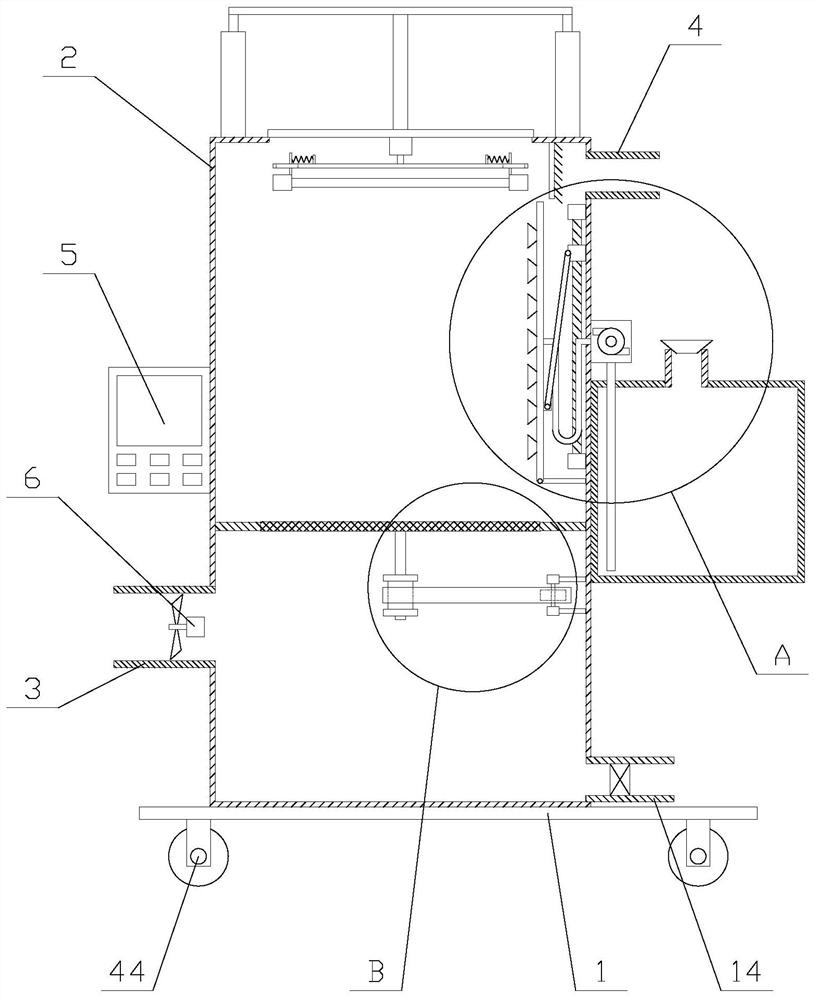
[0025] Such as figure 1 As shown, an air purification system with a dredging function using photocatalyst technology includes a purification device, which includes a bottom plate 1, a casing 2, an air intake pipe 3, an exhaust pipe 4, a controller 5, a processor mechanism and an irradiation mechanism, the housing 2 is fixed above the base plate 1, the air intake pipe 3 and the processor are fixed on one side of the housing 2, the processor is provided with a PLC, and the air intake pipe 3 is provided with a fan 6, The fan 6 is electrically connected to the PLC, the exhaust pipe 4 is arranged on the other side of the upper part of the casing 2, and the irradia...
PUM
Abstract
The invention relates to an air purification system with a dredging function using photocatalyst technology, including a purification device, the purification device includes a bottom plate, a shell, an air intake pipe, an exhaust pipe, a controller, a processor mechanism and an irradiation mechanism, and the irradiation mechanism includes an opening, Cover plate, lifting component, first motor, flat plate, ultraviolet lamp tube and two installation components, processing mechanism includes closed ring, photocatalyst net, rotating component and dredging component, dredging component includes water supply unit, cleaning pipe, direction adjustment unit, drainage Tubes and several nozzles, the air purification system with dredging function using photocatalyst technology irradiates ultraviolet rays to the photocatalyst net through the irradiation mechanism, and can also facilitate the replacement of ultraviolet lamp tubes through the lifting of the plate. Cooperating with the operation, the photocatalyst net can be washed and cleaned to ensure the dredging of the photocatalyst net, thereby improving the air purification effect and improving the practicability of the equipment.
Description
technical field [0001] The invention relates to the field of air purification equipment, in particular to an air purification system with a dredging function using photocatalyst technology. Background technique [0002] Photocatalyst air purification is to use photocatalyst technology to degrade toxic and harmful substances in the air and kill a variety of A purification technique for microorganisms. Photocatalyst air purifiers use this technology to purify the air. [0003] When the existing photocatalyst air purifiers are in use, they need to cooperate with ultraviolet lamps to irradiate ultraviolet rays on the surface of the photocatalyst to produce oxides to decompose harmful substances in the air. Since ultraviolet rays have certain harmful effects on the human body, most ultraviolet rays are fixedly installed in inside the purifier, but when the ultraviolet light reaches the service life, because the ultraviolet light is fixedly installed inside the equipment, it is ...
Claims
Application Information
Patent Timeline
Application Date:The date an application was filed.
Publication Date:The date a patent or application was officially published.
First Publication Date:The earliest publication date of a patent with the same application number.
Issue Date:Publication date of the patent grant document.
PCT Entry Date:The Entry date of PCT National Phase.
Estimated Expiry Date:The statutory expiry date of a patent right according to the Patent Law, and it is the longest term of protection that the patent right can achieve without the termination of the patent right due to other reasons(Term extension factor has been taken into account ).
Invalid Date:Actual expiry date is based on effective date or publication date of legal transaction data of invalid patent.