Bridge road surface multifunctional cutting equipment
A kind of cutting equipment and multi-functional technology, applied in the field of multi-functional cutting equipment for bridge pavement, can solve the problem of locking in the cutting seam, and achieve the effect of convenient dust removal
- Summary
- Abstract
- Description
- Claims
- Application Information
AI Technical Summary
Problems solved by technology
Method used
Image
Examples
specific Embodiment approach 1
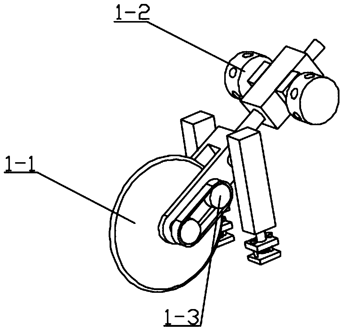
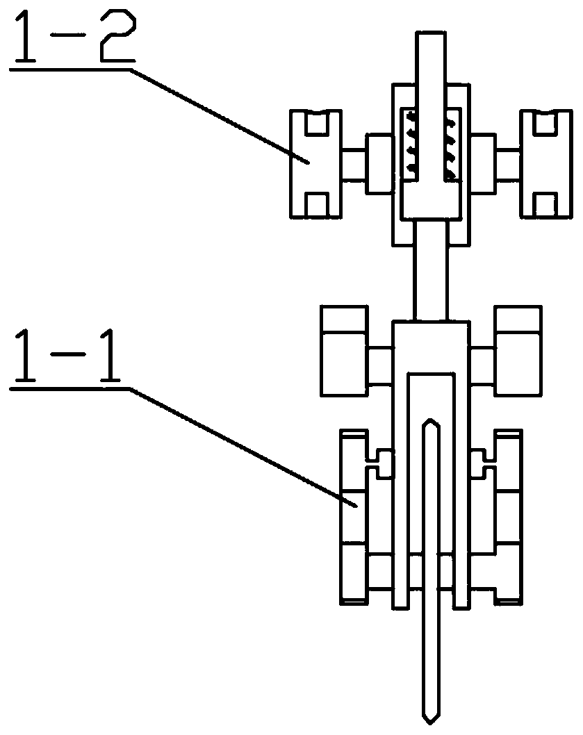
[0042] Combine below figure 1 , figure 2 , image 3 , Figure 4 , Figure 5 , Image 6 , Figure 7 , Figure 8 , Picture 9 , Picture 10 , Picture 11 , Picture 12 , Figure 13 , Figure 14 , Figure 15 , Figure 16 , Figure 17 , Figure 18 , Figure 19 , Picture 20 , Figure 21 , Figure 22 , Figure 23 , Figure 24 , Figure 25 , Figure 26 Explaining this embodiment, the present invention relates to a cutting device, more specifically, a multifunctional cutting device for bridge pavement, including a cutting actuator 1, a limit body mechanism 2, a winding mechanism 3, and a dust cleaning mechanism 4. The device can cut, the device can easily pull out the locked cutting knife, the device can change the cutting angle, the device can wrap the thread, the device can cut the thread, the device can purify the dust generated during cutting, and the device can clean dust more conveniently.
[0043] The cutting execution mechanism 1 is connected with the limiting body mechanism 2, ...
specific Embodiment approach 2
[0045] Combine below figure 1 , figure 2 , image 3 , Figure 4 , Figure 5 , Image 6 , Figure 7 , Figure 8 , Picture 9 , Picture 10 , Picture 11 , Picture 12 , Figure 13 , Figure 14 , Figure 15 , Figure 16 , Figure 17 , Figure 18 , Figure 19 , Picture 20 , Figure 21 , Figure 22 , Figure 23 , Figure 24 , Figure 25 , Figure 26 This embodiment will be described. This embodiment will further explain the first embodiment. The cutting execution mechanism 1 includes a cutting knife support mechanism 1-1, an adjusting wheel mechanism 1-2, a driving mechanism 1-3, and a cutting knife support mechanism 1- 1 is connected to the adjusting wheel mechanism 1-2, and the driving mechanism 1-3 is connected to the cutting knife support mechanism 1-1; the cutting knife support mechanism 1-1 includes the cutting knife 1-1-1, the belt pulley 1-1-2, Cutting knife support 1-1-3, hydraulic cylinder 1-1-4, connecting shaft 1-1-5, middle boss 1-1-6, spring 1-1-7, upper sliding rod ...
specific Embodiment approach 3
[0047] Combine below figure 1 , figure 2 , image 3 , Figure 4 , Figure 5 , Image 6 , Figure 7 , Figure 8 , Picture 9 , Picture 10 , Picture 11 , Picture 12 , Figure 13 , Figure 14 , Figure 15 , Figure 16 , Figure 17 , Figure 18 , Figure 19 , Picture 20 , Figure 21 , Figure 22 , Figure 23 , Figure 24 , Figure 25 , Figure 26 To explain this embodiment, this embodiment will further explain the first embodiment. The limiting body mechanism 2 includes a flanged housing 2-1, a bearing seat 2-2, a limiting housing 2-3, and a pulling seat Mechanism 2-4, support I2-5, handle 2-6, through hole 2-7, built-in spring 2-8, bearing seat 2-2 is connected with flanged box 2-1, limit shell 2-3 Connected to the flanged box 2-1, the pull seat mechanism 2-4 is matched with the limit housing 2-3, the support I2-5 is connected to the flanged box 2-1, and the handle 2-6 is connected to the support I2 -5 is connected, the through hole 2-7 is opened on the limit housing 2-3, the...
PUM
 Abstract
Description
Claims
Application Information
 - R&D
- Intellectual Property
- Life Sciences
- Materials
- Tech Scout
- Unparalleled Data Quality
- Higher Quality Content
- 60% Fewer Hallucinations
Browse by: Latest US Patents, China's latest patents, Technical Efficacy Thesaurus, Application Domain, Technology Topic, Popular Technical Reports.
© 2025 PatSnap. All rights reserved.Legal|Privacy policy|Modern Slavery Act Transparency Statement|Sitemap|About US| Contact US: help@patsnap.com


