Method for treating inferior residual oil by combined process
A combined process, inferior technology, applied in the treatment of hydrocarbon oil, hydrotreating process, petroleum industry, etc., can solve problems such as complex operation
- Summary
- Abstract
- Description
- Claims
- Application Information
AI Technical Summary
Problems solved by technology
Method used
Image

Examples
Embodiment 1
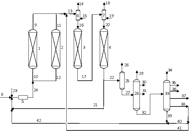
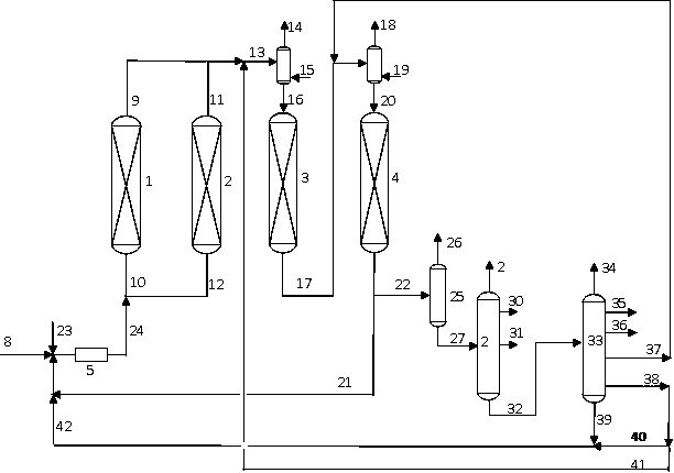
[0082] according to figure 1 In the process flow, the hydrogenation pretreatment reaction zone includes a switchable first hydrogenation pretreatment reaction zone and a second hydrogenation pretreatment reaction zone, the first hydrogenation pretreatment reaction zone is provided with a reactor 1, and the second hydrogenation pretreatment reaction zone is provided with a reactor 1. A reactor 2 is arranged in the second hydrogenation pretreatment reaction zone, and the hydrogenation treatment reaction zone includes a hydrogen mixing tank 6 , a reactor 3 , a hydrogen mixing tank 7 and a reactor 4 arranged in series. According to the material flow direction, the reactor in the hydrogenation pretreatment reaction zone (only one hydrogenation pretreatment reaction zone is online during operation) is filled with catalyst A, catalyst B and catalyst C, and the loading volume ratio of each catalyst is 2:7 : 1. Catalyst B and Catalyst C are installed in the reactor 3 of the hydrotreat...
Embodiment 2
[0088] according to figure 1 In the process flow, the hydrogenation pretreatment reaction zone includes a switchable first hydrogenation pretreatment reaction zone and a second hydrogenation pretreatment reaction zone, the first hydrogenation pretreatment reaction zone is provided with a reactor 1, and the second hydrogenation pretreatment reaction zone is provided with a reactor 1. A reactor 2 is arranged in the second hydrogenation pretreatment reaction zone, and the hydrogenation treatment reaction zone includes a hydrogen mixing tank 6 , a reactor 3 , a hydrogen mixing tank 7 and a reactor 4 arranged in series. According to the material flow direction, the reactor in the hydrogenation pretreatment reaction zone (only one hydrogenation pretreatment reaction zone is online during operation) is filled with catalyst A, catalyst B and catalyst C, and the loading volume ratio of each catalyst is 3:6 : 1. Catalyst B and catalyst C are housed in hydrotreating reaction zone reacto...
Embodiment 3
[0091] according to figure 1 In the process flow, the hydrogenation pretreatment reaction zone includes a switchable first hydrogenation pretreatment reaction zone and a second hydrogenation pretreatment reaction zone, the first hydrogenation pretreatment reaction zone is provided with a reactor 1, and the second hydrogenation pretreatment reaction zone is provided with a reactor 1. A reactor 2 is arranged in the second hydrogenation pretreatment reaction zone, and the hydrogenation treatment reaction zone includes a hydrogen mixing tank 6 , a reactor 3 , a hydrogen mixing tank 7 and a reactor 4 arranged in series. According to the material flow direction, the reactor in the hydrogenation pretreatment reaction zone (only one hydrogenation pretreatment reaction zone is online during operation) is filled with catalyst A, catalyst B and catalyst C, and the loading volume ratio of each catalyst is 4:5 : 1. Catalyst B and Catalyst C are installed in the reactor 3 of the hydroproce...
PUM
| Property | Measurement | Unit |
|---|---|---|
| specific surface area | aaaaa | aaaaa |
| specific surface area | aaaaa | aaaaa |
Abstract
Description
Claims
Application Information
 - R&D
- Intellectual Property
- Life Sciences
- Materials
- Tech Scout
- Unparalleled Data Quality
- Higher Quality Content
- 60% Fewer Hallucinations
Browse by: Latest US Patents, China's latest patents, Technical Efficacy Thesaurus, Application Domain, Technology Topic, Popular Technical Reports.
© 2025 PatSnap. All rights reserved.Legal|Privacy policy|Modern Slavery Act Transparency Statement|Sitemap|About US| Contact US: help@patsnap.com