Automatic seedling transplanting machine driving device

An automatic seedling transplanter and driving device technology, applied in electromechanical devices, transplanting machinery, planting methods, etc., can solve the problems of slow seedling transplanting speed, soil and root impact, etc., to avoid damage to the root system and improve the effect of soil breaking.

Inactive Publication Date: 2019-11-05
WEIFANG UNIV OF SCI & TECH
View PDF8 Cites 2 Cited by
  • Summary
  • Abstract
  • Description
  • Claims
  • Application Information

AI Technical Summary

Problems solved by technology

[0004] The seedling transplanting machine is designed for the convenience of transplanting seedlings. When the shovel head of the existing seedling transplanting machine moves, the speed of up and down movement is consistent, which makes it difficult to effectively impact the soil and root system when breaking the soil. , so that the transplanting speed is slower

Method used


Image

  • Automatic seedling transplanting machine driving device
  • Automatic seedling transplanting machine driving device
  • Automatic seedling transplanting machine driving device

Examples


Embodiment 1

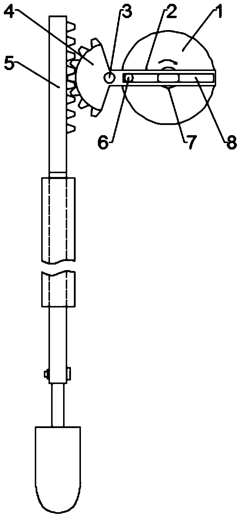
[0019] see Figure 1~2 , in the embodiment of the present invention, a driving device for an automatic seedling transplanting machine includes a motor 7 and a driving member 5, a disk 1 is installed at the end of the output shaft of the motor 7, and a swing rod 2 is connected to the front side of the disk 1 , the outer side of the front end of the disc 1 is integrally provided with a cylindrical pin 6, the swing rod 2 is provided with a chute 8 for the cylindrical pin 6 to penetrate and slide, the end of the cylindrical pin 6 is pierced with a limit pin, the function of the limit pin It is to prevent the cylindrical pin 6 from being separated from the chute 8 due to external force. The left end of the swing rod 2 is welded and fixed with a sector gear 4. The center of the sector gear 4 is pierced with a positioning pin 3. There is a gap between the positioning pin and the center of the sector gear 4. Cooperate, one side of the sector gear 4 is provided with a drive member 5, t...

Embodiment 2

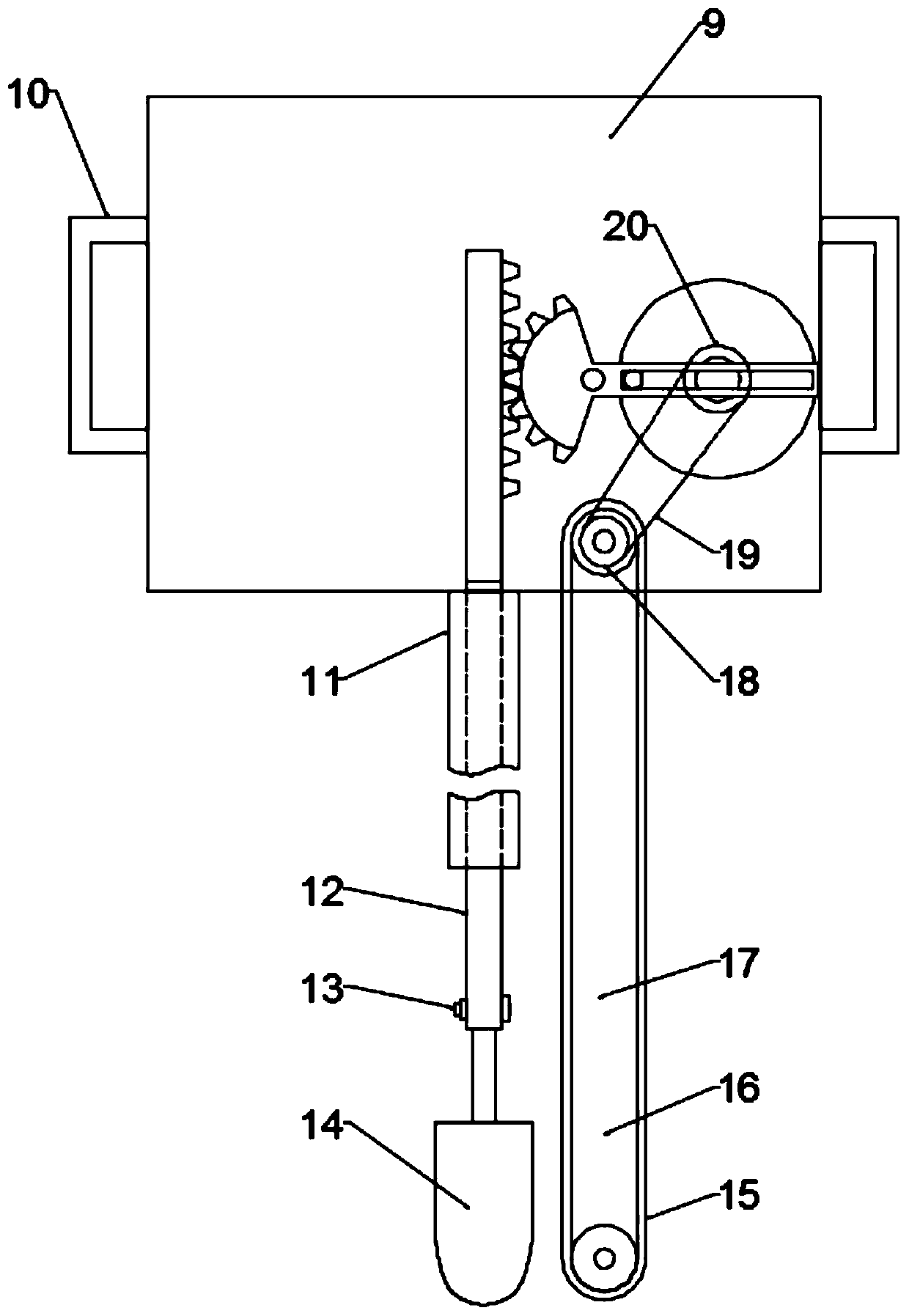
[0021] see image 3 , this embodiment discloses an automatic seedling transplanting machine, including the automatic seedling transplanting machine driving device described in embodiment 1, and also includes a frame 9, a guide sleeve 11, a mounting rod 12 and a shovel head 14, the driving device Installed in the frame 9, the two ends of the frame 9 are welded and fixed with handles 10, the bottom of the frame 9 is welded and fixed with a guide sleeve 11, the bottom of the driver 5 is welded and fixed with a mounting rod 12, and the other end of the mounting rod 12 passes through the guide sleeve 11 And extend to below the guide sleeve 11, the installation rod 12 is matched with the guide sleeve 11 clearance, the shovel head 14 is installed on the bottom end of the installation rod 12 by the bolt 13, and the chain saw 17 is installed on the described frame 9, and the chain saw 17 comprises a chain plate 16, chain wheel and saw blade 15, chain plate 16 is welded and fixed on the...


PUM


Abstract

The invention discloses an automatic seedling transplanting machine driving device. The device comprises a motor and a driving component, a disc is installed at the end of an output shaft of the motor, a swing rod is cooperatively connected to the front side of the disc, a sector gear is fixedly to the left end of the swing rod through welding, a locating pin penetrates through the center of a circle of the sector gear and is in clearance fit with an opening formed in the center of the circle of the sector gear, the driving component is arranged on one side of the sector gear, and the drivingcomponent is a rack which is meshed with the sector gear. The invention further discloses a seedling transplanting machine containing the driving device. Accordingly, by means of cooperation of the disc, the swing rod, the sector gear and the rack and the quick-return characteristics, a shovel head moves downwards, the groundbreaking speed is increased, thus the soil is impacted, and the groundbreaking effect is improved; meanwhile, by arranging a chain saw, roots in soil can be cut off rapidly, root damage is avoided, and by cooperating with the shovel head, cutting is conducted more rapidlyand efficiently, and labor is saved.

Description

technical field [0001] The invention relates to the technical field of plant planting, in particular to a driving device for an automatic seedling transplanting machine. Background technique [0002] Whether it is crop planting, ornamental planting or greening planting, its development momentum is remarkable, and in the current big market situation, the turnover and transportation of plants are inseparable from transplanting seedlings. [0003] When carrying out seedling transplanting operation now, mostly adopt the seedling transplanting frocks and tools such as hoes or shovels, wherein, for small and medium-sized plants, the situation that the seedling transplanting shovel is positioned at the seedling transplanting utensil is in the majority. [0004] The seedling transplanting machine is designed for the convenience of transplanting seedlings. When the shovel head of the existing seedling transplanting machine moves, the speed of up and down movement is consistent, which...

Claims


Application Information

Patent Timeline
Patent Type & Authority Applications(China)
IPC IPC(8): A01C11/02A01G23/06H02K7/116H02K7/06
CPCA01C11/02A01G23/06H02K7/06H02K7/1163
Inventor 马丽丽
Owner WEIFANG UNIV OF SCI & TECH
Why Eureka
Try Eureka