Composite optical system adopting double internal lenses

An optical system and inner lens technology, applied in the field of composite optical systems, can solve the problems of insufficient uniformity, low light efficiency, and can not meet the requirements of the designer, and achieve the goal of improving uniformity, ensuring uniformity and reducing diffusion loss. Effect

Pending Publication Date: 2019-11-01
MAGNETI MARELLI AUTOMOTIVE COMPONENTS WUHU
View PDF0 Cites 0 Cited by
  • Summary
  • Abstract
  • Description
  • Claims
  • Application Information

AI Technical Summary

Problems solved by technology

[0003] Initially, using a reflective structure alone combined with two defocused light sources to achieve different functions was widely used in compound optical systems due to its good light efficiency, but the uniformity was insufficient.
As customers have more stringent requirements on the lighting effect of car lights in recent years, the above-mentioned reflective structure can no longer meet the requirements of designers.
The light guide is favored by designers as a compound optical system because of its good uniformity. The optical system that uses the light guide alone and combines two defocused light sources at the light input end to achieve the multiplexing effect is beginning to be favored due to its improved uniformity compared with the previous reflective structure. It is used, but at the same time, because its light efficiency is too low, the risk of optical input and heat resistance is doubled, so it is only used in high-end cars with large lamp body space.

Method used


Image

  • Composite optical system adopting double internal lenses
  • Composite optical system adopting double internal lenses
  • Composite optical system adopting double internal lenses

Examples


Embodiment Construction

[0024] In order to deepen the understanding of the present invention, the present invention will be further described below in conjunction with the examples, which are only used to explain the present invention, and do not constitute a limitation to the protection scope of the present invention.

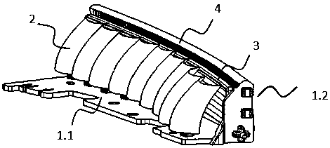
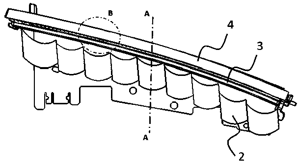
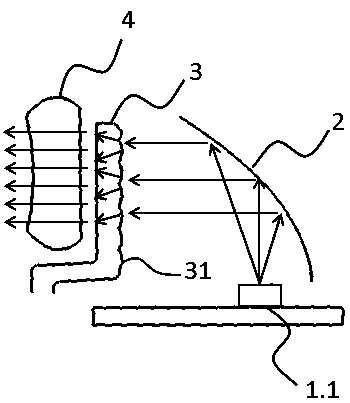
[0025] Such as Figure 1-5 As shown, this embodiment provides a compound optical system using a double inner lens, including a light source 1.1, a light source 2 1.2, a reflective bowl 2, a transparent inner lens 3 and a wide light guide 4, wherein the wide light guide 4 is different from the commonly used The circular light guide, in this embodiment, is an elliptical wide light guide, which can increase the light transmittance and improve the optical efficiency of the system. The reflective bowl 2 is a paraboloid without optical patterns, one side of the transparent inner lens 3 has horizontal stripes 31 for optical effects, and the other side is a smooth surface without optical pat...


PUM


Abstract

The invention provides a composite optical system adopting double internal lenses; the composite optical system comprises a light source I, a light source II, a reflection bowl, a transparent internallens and a wide light guide. The wide light guide serves as the function of an internal lens. Vertical stripes are arranged on the wide light guide. The transparent internal lens is arranged betweenthe wide light guide and the reflection bowl; transverse stripes are arranged on the transparent internal lens; the light source II is placed at the light inlet end of the wide light guide, so that one optical function is realized; the light source I is placed at the focal point of the reflection bowl, the light emitted by the light source I is converged through the paraboloid of the reflection bowl and is emitted in parallel to pass through the transverse stripes in the transparent internal lens to be subjected to diffusion of the first time; light penetrates through air to reach the wide light guide and passes through the vertical stripes on the rear surface to be subjected to diffusion of the second time; and next, the light is emitted, so that the other optical function of the multiplexing system is realized. The uniformity is ensured. The diffusion loss caused by depth is reduced, and meanwhile, the optical efficiency is improved and the diffusion angle of light is increased through the whole optical system.

Description

technical field [0001] The invention relates to the field of automotive lighting, in particular to a composite optical system using double inner lenses. Background technique [0002] At present, with the popularization of LED light sources in car lights, more possibilities are provided for the design of car lights. In view of the fact that the function of the current car light is no longer lighting and indicating, but more to realize the concept of shape design, and the design of car light shape tends to be concise, leaving less space for design, and the reuse of car light functions into a trend. [0003] Initially, using a reflective structure alone combined with two defocused light sources to achieve different functions is widely used in compound optical systems due to its good light efficiency, but the uniformity is insufficient. As customers have stricter requirements on the lighting effect of car lights in recent years, the above-mentioned reflective structure can no ...

Claims


Application Information

Patent Timeline
Patent Type & Authority Applications(China)
IPC IPC(8): F21S43/236F21S43/20F21S43/31F21V5/04F21Y115/10F21W103/10F21W103/20F21W103/35F21W103/45F21W103/55
CPCF21S43/20F21S43/236F21S43/31F21V5/04F21W2103/10F21W2103/20F21W2103/35F21W2103/45F21W2103/55F21Y2115/10
Inventor 仝旋
Owner MAGNETI MARELLI AUTOMOTIVE COMPONENTS WUHU
Why Eureka
Try Eureka