


Quick Research
Generate reliable direction feasibility study reports for your R&D in just a few steps.

Technical Q&A
Discover and master advanced knowledge NOW. Basics, ideas, possibilities, all at once.

Find Solutions
As an expert in R&D theories, this can generate solutions to your technical problems instantly.

Evaluate Feasibility
Analyze your overall solution with one click, know your potential R&D risks in advance.

Monitor Landscape
Get weekly tech updates, stay abreast of the latest tech innovations and key insights.
Device combining waste-heat recovery and white elimination with wastewater concentration
A technology for wastewater concentration and waste heat recovery, applied in heat recovery systems, heating water/sewage treatment, gaseous discharge wastewater treatment, etc., can solve problems such as reduced unit efficiency, increased dust removal equipment load, low operating costs, etc., to achieve a good society. and economic impact, reducing the dust content of the flue gas, eliminating the effect of wet plume
- Summary
- Abstract
- Description
- Claims
- Application Information
AI Technical Summary
Problems solved by technology
Method used
Image

Examples
Embodiment 1
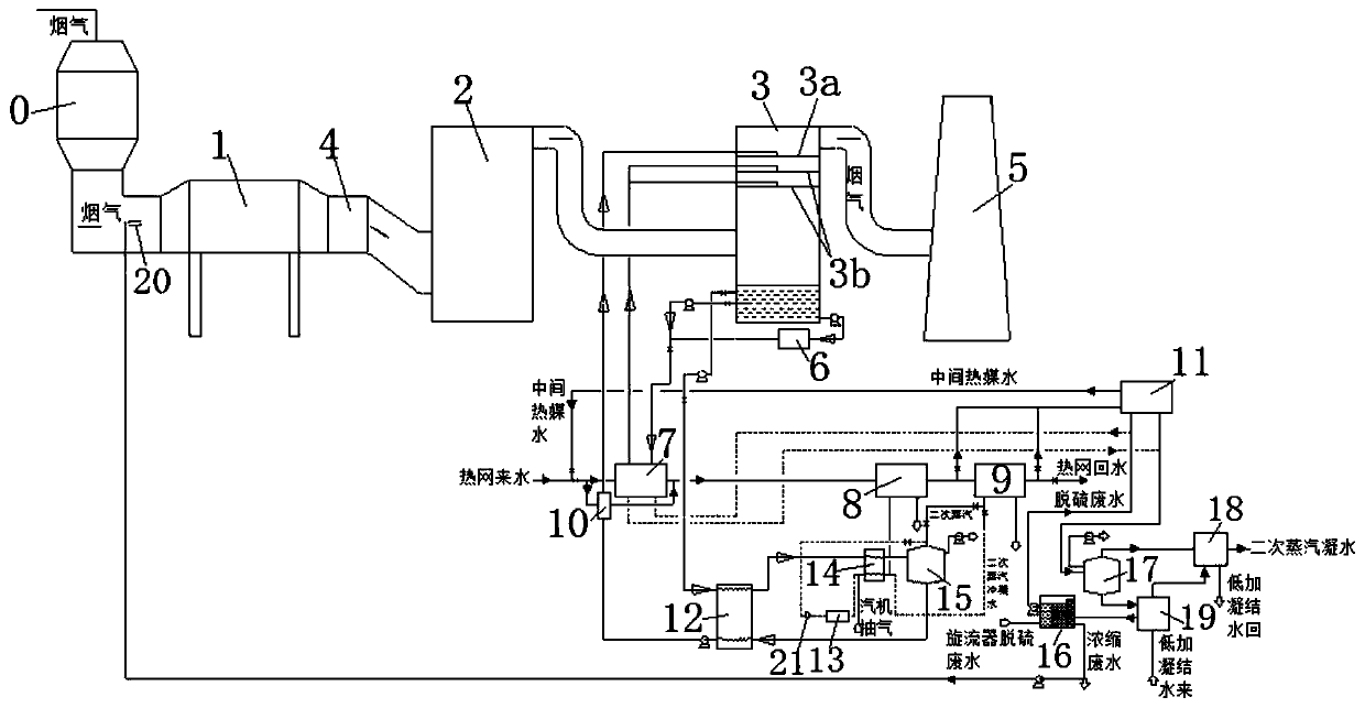
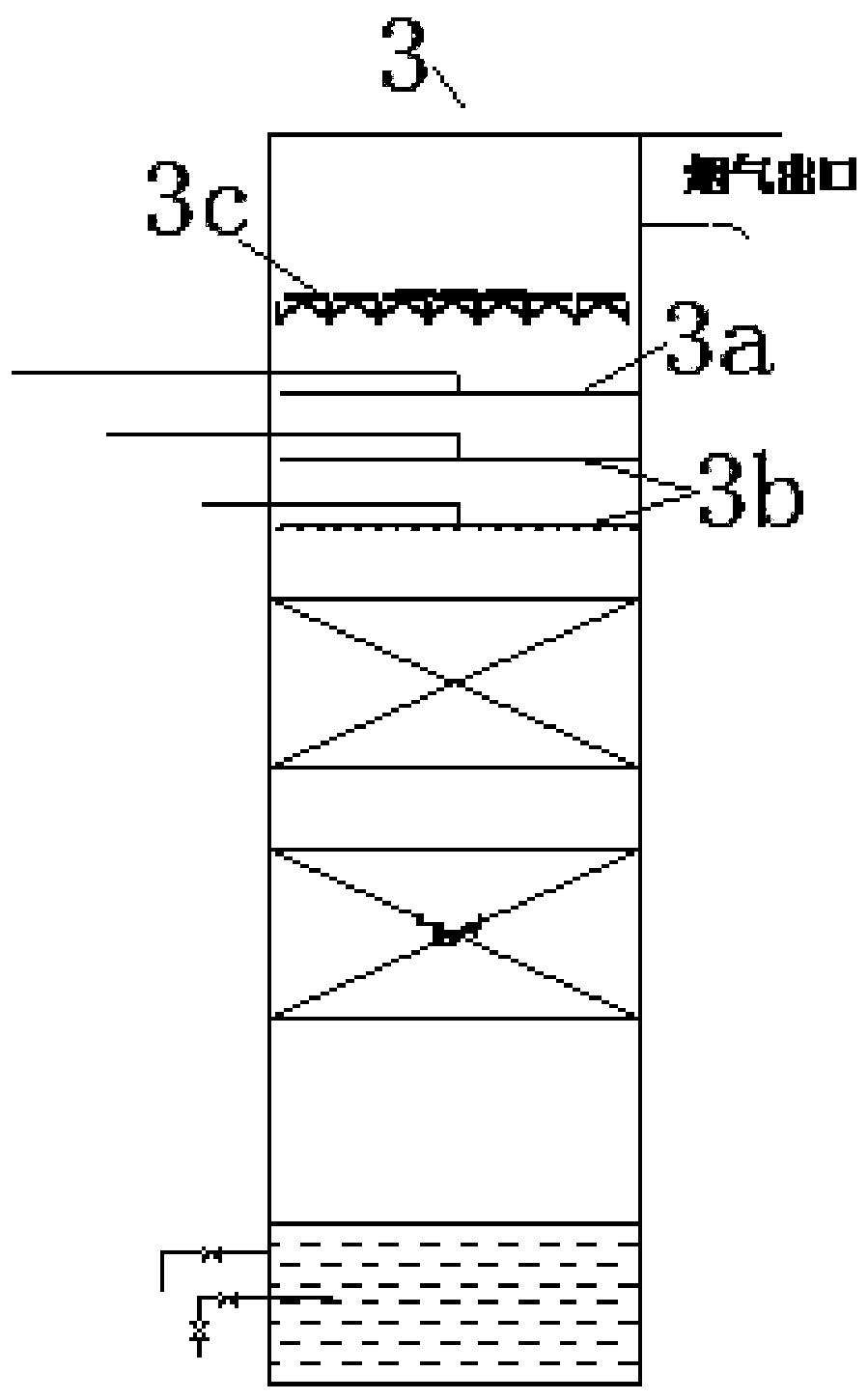
[0045] This embodiment provides a device for waste heat recovery and whitening combined with waste water concentration, such as figure 1 , 3 , 4 and 5, the absorption heat pump system includes the air preheater 0, the dust removal unit 1, the economizer 4, the desulfurization unit 3 and the chimney 5 which are connected in sequence, and also includes the first circulation loop and the first circulation loop The first heat exchanger 7 on the top, the liquid inlet end of the first circulation loop communicates with the lower part of the absorption unit 3, and the liquid outlet communicates with the upper part of the absorption unit 3; in this embodiment, the dust removal unit 1 is an electric precipitator, The economizer 4 is a low-temperature economizer, and the desulfurization unit 2 is a desulfurization tower; the absorption unit 3 can be an absorption tower, and the absorption tower can be an empty tower or a packed tower. When it is a packed tower, the packing can be single...
Embodiment 2
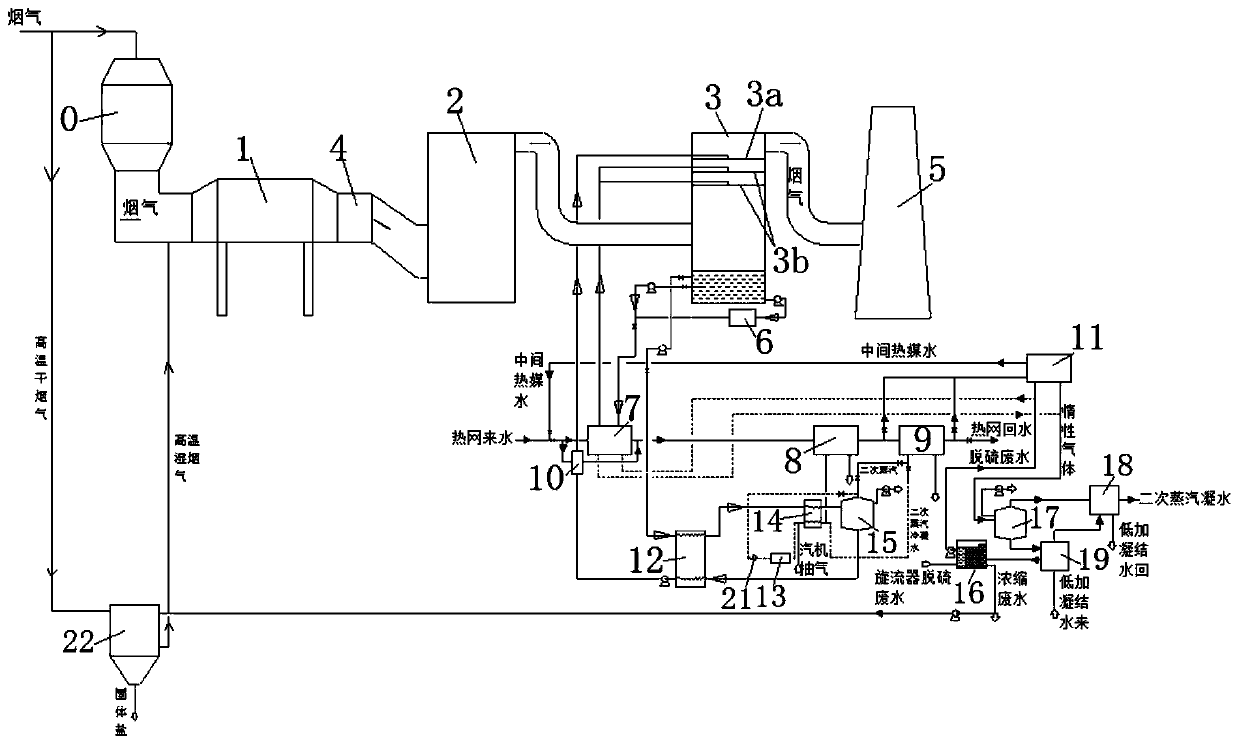
[0060] This embodiment provides a device for waste heat recovery and whitening combined with waste water concentration, such as figure 2 As shown, on the basis of the above-mentioned embodiment 1, as a variable embodiment, the evaporative drying system is a rotary spray evaporator 22, the upper part of which is provided with a high-temperature dry flue gas inlet, and along the flow direction of the flue gas, the high-temperature dry flue gas The inlet is connected with the upstream flue of the air preheater 0, so that the high-temperature dry flue gas in the upstream flue of the air preheater 0 enters the rotary spray evaporator to exchange heat with the concentrated desulfurization wastewater; specifically, the high-temperature dry flue gas inlet and the air The inlet flue of preheater 0 is connected;
[0061] The lower part of the rotary spray evaporator is provided with a high-temperature wet flue gas outlet, and the high-temperature wet flue gas outlet communicates with t...
Embodiment 3
[0064] This embodiment provides a device for waste heat recovery and whitening combined with waste water concentration. On the basis of the above-mentioned embodiment 1 or 2, it also includes a condenser 18, which communicates with the secondary steam outlet on the upper part of the waste water flash tank 17. The condenser 18 is also communicated with the waste water cooler 19, so that the heat exchange medium from the raised temperature in the waste water cooler 19 enters the condenser 18, and exchanges heat again with the secondary steam from the waste water flash tank 17;
[0065] Further, a fourth heat exchanger 10 is also included, which is arranged on the second circulation loop, and is used to exchange heat for the concentrated solution again.
[0066] In the heating season, the intermediate heat medium water exchanges heat with the absorption liquid from the absorber, and the heat network water that exits the first heat exchanger (primary heat exchanger) and enters the ...
PUM
 Abstract
Description
Claims
Application Information
 - R&D Engineer
- R&D Manager
- IP Professional
- Industry Leading Data Capabilities
- Powerful AI technology
- Patent DNA Extraction
Browse by: Latest US Patents, China's latest patents, Technical Efficacy Thesaurus, Application Domain, Technology Topic, Popular Technical Reports.
© 2024 PatSnap. All rights reserved.Legal|Privacy policy|Modern Slavery Act Transparency Statement|Sitemap|About US| Contact US: help@patsnap.com