Deformation joint later-burying type waterstop belt and mounting method thereof

An installation method and deformation joint technology, which are applied in building components, building insulation materials, buildings, etc., can solve the problems of easy damage to filler strips, failure of rubber waterstops, short service life, etc., and achieve good welding fixing effect and welding. Mature, the effect of improving waterproof performance

Pending Publication Date: 2019-10-29
深圳市永固建筑科技有限公司
View PDF1 Cites 1 Cited by
  • Summary
  • Abstract
  • Description
  • Claims
  • Application Information

AI Technical Summary

Problems solved by technology

[0003] At present, rubber waterstops for deformation joints in domestic subways, railways, municipal ducts and other underground projects mostly have serious defects of failure. For example, the Chinese patent with the notification number CN101705696B discloses a method for preventing and controlling leakage of deformation joints in basements, using clay, Water, oil, and additives form soft plastic materials, pour them into sealed bags to make soft plastic sausage filling strips, apply waterproof adhesive to the deformation joints and the walls where the waterstops are buried, and then fill the deformation joints with filling strips. Cover the elastic pressure strip, press the gasket nut to fix
It has the advantages of easy material acquisition, low price, and simple installation; however, it mainly uses soft filling strips to achieve waterproof purposes. On the one hand, this waterproof method has the problem of short service life, and the filling strips are prone to damage as time increases. , on the other hand, there are defects that are difficult to repair after the soft filling strip is damaged and leaks, which needs further improvement

Method used


Image

  • Deformation joint later-burying type waterstop belt and mounting method thereof
  • Deformation joint later-burying type waterstop belt and mounting method thereof
  • Deformation joint later-burying type waterstop belt and mounting method thereof

Examples


Embodiment 1

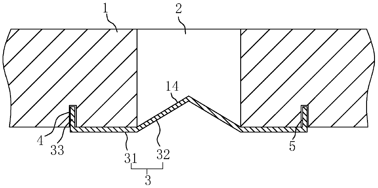
[0045] Example 1: A buried waterstop behind a deformation joint, such as figure 1 As shown, it includes a deformation joint 2 reserved on the concrete wall 1, and a water stop plate 3 is provided on the side of the deformation joint 2 facing the interior, and the water stop plate 3 includes a V-shaped bending part in the middle. 32 and the wing plates 31 on both sides, wherein the bent part 32 and the wing plate 31 are integrally set and fixed on the surface of the concrete wall 1 through the wing plate 31; there are installation joints on the surface of the concrete wall 1 on both sides of the deformation joint 2 4. The width of the installation seam 4 is 5 mm, and the depth of the seam is 20-30 mm. In this embodiment, the seam depth of the installation seam 4 is 25 mm. 4 Inserting the plug-in part 33, by injecting the anchoring agent 5 in the installation seam 4, the model of the anchoring agent 5 is GCYY-201, and fixing the water-stop plate 3 after the anchoring agent 5 sol...

Embodiment 2

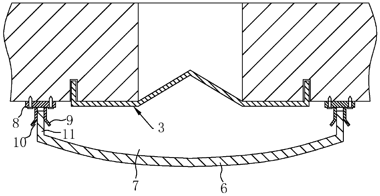
[0049] Example 2: A buried waterstop behind a deformation joint, such as image 3 As shown, the main difference from Embodiment 1 is that an additional water receiving plate 6 is added. The water receiving plate 6 is arranged on the indoor side of the water stop plate 3. The water receiving plate 6 is U-shaped and forms a water receiving tank 7. A base 8 is arranged on the surface of the concrete wall 1, and the base 8 is fixed on the concrete wall 1 by screws, and polyurethane waterproof glue is applied at the joint between the base 8 and the concrete wall 1, which is The base 8 ensures the waterproofness of the connection between the base 8 and the concrete wall 1 while reinforcing; There are inserts 11 that fit into the slots 10 at the two side edges of the two sides; through the further setting of the water-receiving plate 6, a double waterproof effect can be achieved, even if the water-stopping plate 3 accidentally leaks, the water can be caught by the water Plate 6 unde...

Embodiment 3

[0050] Example 3: A buried waterstop behind a deformation joint, such as Figure 4 and Figure 5 As shown, the difference between it and Embodiment 1 is mainly that the insertion portion 33 is tapered, and the width of the insertion portion 33 gradually increases from one end away from the wing plate 31 to the other end, and in the horizontal direction at the end of the insertion portion 33 The protruding part 12 protrudes outward, so that on the one hand, it is convenient for the insertion part 33 to be plugged into the installation seam 4, and on the other hand, the protruding part 12 is laterally trapped in the solidified anchoring agent 5, which can play a good role in preventing detachment, and The amount of anchoring agent 5 at the bottom wall of the installation slot 4 is larger, so that the fixation of the insertion part 33 is better.

[0051] In addition, glue grooves 13 are arranged at intervals on the surface of the wing plate 31 close to the insertion portion 33 f...


PUM

PropertyMeasurementUnit
Plate thicknessaaaaaaaaaa

Abstract

The invention discloses a deformation joint later-burying type waterstop belt and a mounting method thereof. The belt comprises a semi-flexible semi-rigid waterstop plate which is arranged on the deformation joint of a concrete wall, the waterstop plate is located on an opening, close to the indoor side, of the deformation joint and is fixed to the concrete wall, the middle of the waterstop plateis bent to be suitable for telescopic deforming of concrete on two sides, during construction, the needed waterstop plate is determined through measuring in advance, the waterstop plate is fixed through an anchorage agent, the water leakage appearing in the connecting position of the waterstop plate and the concrete can be effectively prevented, the semi-flexible semi-rigid waterstop plate has thebetter durability relative to the traditional rubber type flexible material, the problem that the traditional rubber type flexible material has the poor durability can be solved, the waterstop platehas the certain elastic deforming capacity, and can be suitable for deforming of uneven sedimentation of the concrete wall, the waterstop plate is not prone to damage due to sedimentation stretching,when the leakage appears in the waterstop plate subsequently, repairing can be achieved directly through welding, and the aim of facilitating repair is achieved.

Description

technical field [0001] The invention relates to the field of waterproofing of deformation joints, more specifically, it relates to a water stop belt embedded behind deformation joints and an installation method thereof. Background technique [0002] Deformation joints are the general term for expansion joints, settlement joints and seismic joints. Buildings often deform under the action of external factors, leading to cracking or even destruction. Deformation joints are structural joints reserved for this situation. [0003] At present, rubber waterstops for deformation joints in domestic subways, railways, municipal pipes and other underground projects mostly have serious defects of failure. For example, the Chinese patent with the notification number CN101705696B discloses a method for preventing and controlling leakage of deformation joints in basements, using clay, Water, oil, and additives form soft plastic materials, which are poured into sealed bags to make soft plast...

Claims


Application Information

Patent Timeline
IPC IPC(8): E04B1/68
CPCE04B1/6806E04B1/6803
Inventor 聂慧徐利洪王震
Owner 深圳市永固建筑科技有限公司
Why Eureka
Try Eureka