
Landing device for vertical lifting aircraft and ship

A vertical lift and aircraft technology, applied in the field of ships, can solve the problems of hitting the deck, not suitable for lift, and not strong in versatility, so as to achieve the effect of buffering the impact force and avoiding strong vibration

Pending Publication Date: 2019-10-29
魏荣亮
View PDF0 Cites 8 Cited by
  • Summary
  • Abstract
  • Description
  • Claims
  • Application Information

AI Technical Summary

Problems solved by technology

[0006] At present, the landing gear of helicopters mainly includes three types: skid type, wheel type, skid and wheel combination type, wherein the skid type, skid and wheel combination type landing gear has no shock absorption effect, although the wheel type landing gear has certain damping effect. Shock effect, but because of the heavy weight, the shock absorption effect is not ideal
Regardless of the helicopter with skid type or wheeled landing gear, there are certain difficulties in landing helicopters at present
The main problem of the three existing landing methods is that they are not very versatile. The pull-down method can better solve the problem of helicopter landing in sea conditions below level 6, but it is only suitable for large helicopters with high lift, not suitable for small and medium-sized helicopters with insufficient lift. Helicopter; harpoon-grid type (only suitable for small helicopters of 4 ton to 5 tons) and landing net type helicopter landing deck are all rigid landing decks, which are only suitable for sea conditions below level 5, because the ship is swaying on the sea surface Shaking and undulating, the helicopter is easy to hit the deck directly when it lands vertically
In addition, if the falling speed of the helicopter is not well controlled during the landing process, the moment the helicopter stops on the deck, it will also collide with the deck with a large impact, resulting in an accident. one of the higher
At present, the vertical lift unmanned aircraft can only use the tethered type to land on the unmanned ship. Due to the limitation of the length of the tethered rope, the vertical lift unmanned aircraft cannot be far away from the unmanned ship when it is used, which limits the role of the unmanned aircraft.

Method used


Image

  • Landing device for vertical lifting aircraft and ship
  • Landing device for vertical lifting aircraft and ship
  • Landing device for vertical lifting aircraft and ship

Examples


no. 1 example

[0075] The ship landing device of this embodiment is mainly applied to the landing of vertical lift aircraft such as helicopters and vertical lift unmanned aerial vehicles on ships, so as to avoid landing accidents.

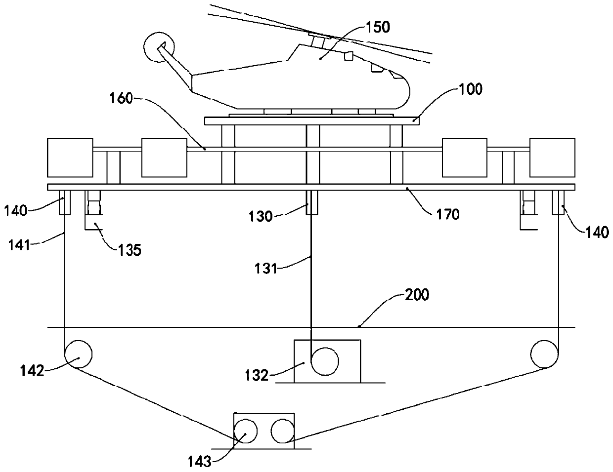
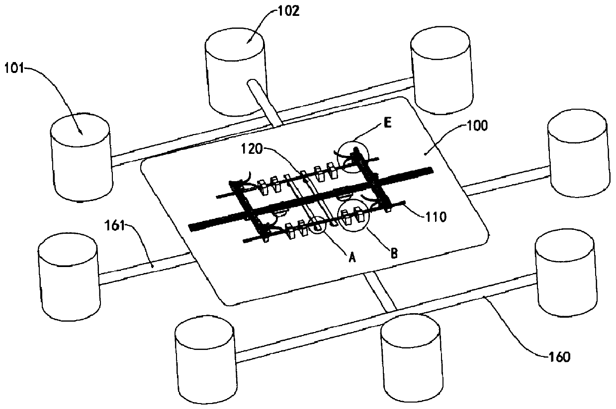
[0076] see figure 1 , the ship includes a hull, the hull is provided with a deck 200, and the lift-off platform is arranged on the deck 200. The lift-off platform of the present embodiment includes a three-layer structure, which is an upper platform 100, a power plant, and a power plant that are sequentially arranged from top to bottom. The layer 160 and the connection layer 170 are fixedly connected by rigid materials, such as steel pipes, among the three layers. The aircraft 150 is locked on the upper platform 100 and lands on the deck 200 together with the lift-off platform, so that the aircraft 150 can be prevented from directly landing on the deck 200 and the rigid collision between the aircraft 150 and the violently shaking deck 200 can be avoided.

[0077...

no. 2 example

[0109] see Figure 16 , the ship in this embodiment has a hull, the hull is provided with a deck 350 , and a lift-off platform 300 is arranged above the deck 350 , and the aircraft 380 can land on the lift-off platform 300 . A magnet 381 is disposed under the belly of the aircraft 380 , preferably, the magnet 381 is flat and has a large area. The landing gear of the aircraft 380 is a skid type landing gear 382 , of course, the aircraft 380 may also adopt a wheel type landing gear.

[0110] In this embodiment, the lift-off platform 300 includes an upper platform 305, a power plant layer 301 and a connecting layer 302. Power devices such as rotors or turbofan engines are arranged on the power plant layer 301. For example, a rotor mounting frame 303 is set on the power plant layer 301 and The turbofan engine mounting frame 304 is driven by the power unit to raise or lower the lift-off platform 300 . In addition, a main probe 330 and a plurality of auxiliary probes 340 are arran...

no. 3 example

[0117] The ship of this embodiment has a hull, a deck is provided on the hull, and a lift-off platform is arranged above the deck, and the aircraft can land on the lift-off platform. Power devices such as rotors or turbofan engines are arranged on the lift-off platform to drive the lift-off platform to rise or fall. In addition, a main probe and multiple auxiliary probes are arranged under the lift-off platform. A main drop cable is arranged in the main probe tube, an auxiliary drop cable is arranged in the auxiliary probe tube, the main drop cable is wound on the main pull winch, and the auxiliary drop cable is wound on the auxiliary drop winch. Moreover, the landing device also includes a cable winch arranged below the deck, the power cable is connected to the cable winch, and the cable winch can release or recover the power cable.

[0118] see Figure 19 and Figure 20 , The locking device of this embodiment includes a telescopic rod 400, the telescopic rod 400 is a hydr...


PUM


Abstract

The invention provides a landing device for a vertical lifting aircraft and a ship. The landing device comprises a lift-off platform, wherein a plurality of power devices used for driving the lift-offplatform to ascend or descend are arranged on the lift-off platform, and a locking device for locking the aircraft is arranged on the lift-off platform; the locking device used for locking the aircraft is arranged on the lift-off platform; a power cable and a main probe pipe are arranged below the lift-off platform, and a main pull-off cable is arranged in the main probe pipe; and a damping landing frame is further arranged below the lift-off platform. The ship is provided with the landing device. According to the landing device, large impact on a deck when the aircraft lands on the deck canbe avoided, and the landing safety of the aircraft is improved.

Description

technical field [0001] The invention relates to the field of landing aids for ship-borne vertical lift aircraft, in particular to a landing device for vertical lift aircraft and a ship with the landing device. Background technique [0002] Ship-borne vertical lift aircraft, such as helicopters and unmanned aerial vehicles, need to rely on the landing device when landing on the ship. However, the existing landing device mainly makes the aircraft perform a rigid landing on the ship. Taking helicopters as an example, the landing devices of helicopters mainly include three types of landing devices: "pull-down" type, "harpoon-grid" type, and "landing aid net" type. [0003] The drag-and-drop landing device is mainly composed of the index, index winch, main probe, tail probe, and the drag and drop winch, clamping mechanism and control room on the ship. When the helicopter is ready to land, the helicopter hovers at a height of 6 to 8 meters above the flight deck, releases the main...

Claims


Application Information

Patent Timeline
Patent Type & Authority Applications(China)
IPC IPC(8): B64F1/00B64F1/02B64F1/12
CPCB64F1/007B64F1/02B64F1/12
Inventor 魏荣亮
Owner 魏荣亮
Learn More