
Lateral core-pulling mechanism capable of pushing and returning on oblique plane and method

A lateral core-pulling and push-out mechanism technology, applied in the field of molds, can solve the problems of easy interference in laterally-molded parts extraction and reset, increased operating procedures, long core-pulling distance, etc.

Inactive Publication Date: 2019-10-29
CHANGZHOU INST OF TECH
View PDF5 Cites 0 Cited by
  • Summary
  • Abstract
  • Description
  • Claims
  • Application Information

AI Technical Summary

Problems solved by technology

Motorized core-pulling has high productivity and is the most widely used in production, but its structure is complex, parts processing is cumbersome, assembly accuracy is low, mechanism stability is poor, and interference is likely to occur when laterally formed parts are drawn and reset
[0006] The hydraulic (or pneumatic) lateral core-pulling mechanism relies on the piston of the hydraulic cylinder or cylinder to move back and forth to pull out and reset the laterally formed parts. procedures, special hydraulic (or pneumatic) pipelines must be designed and equipped with a complete set of hydraulic (or pneumatic) devices, and the economic cost is relatively high

Method used


Image

  • Lateral core-pulling mechanism capable of pushing and returning on oblique plane and method
  • Lateral core-pulling mechanism capable of pushing and returning on oblique plane and method
  • Lateral core-pulling mechanism capable of pushing and returning on oblique plane and method

Examples


Embodiment Construction

[0042] The present invention will be described in further detail below in conjunction with the accompanying drawings.

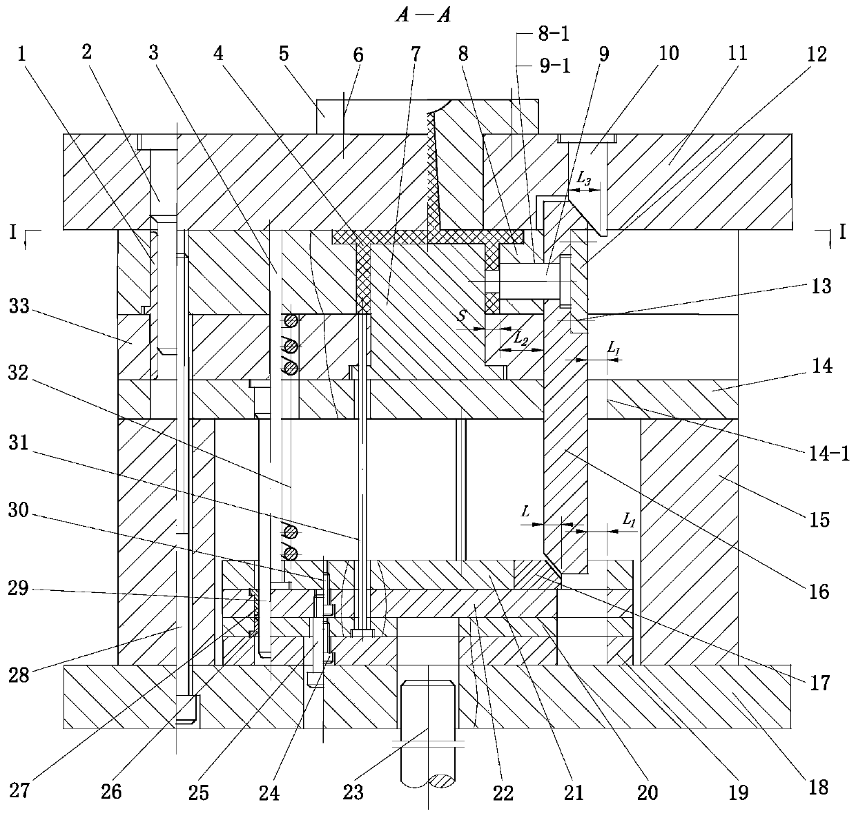
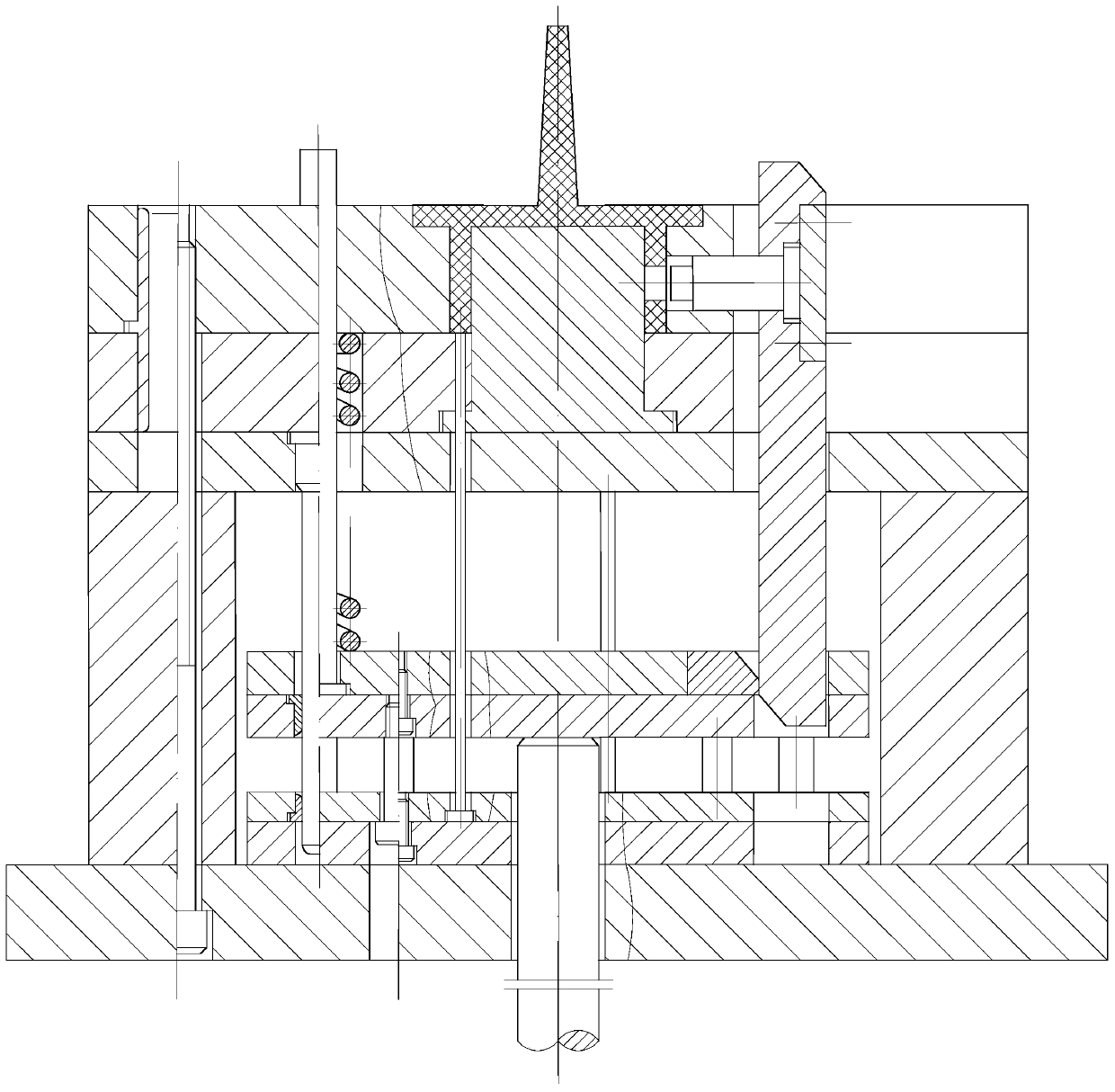
[0043] This embodiment is used for injection molding mould, and mold is installed on the horizontal injection machine. After the injection molding is completed, under the action of the mold opening mechanism of the injection machine, the movable mold part moves along the figure 1 The shown parting surface I-I retreats to the set position.

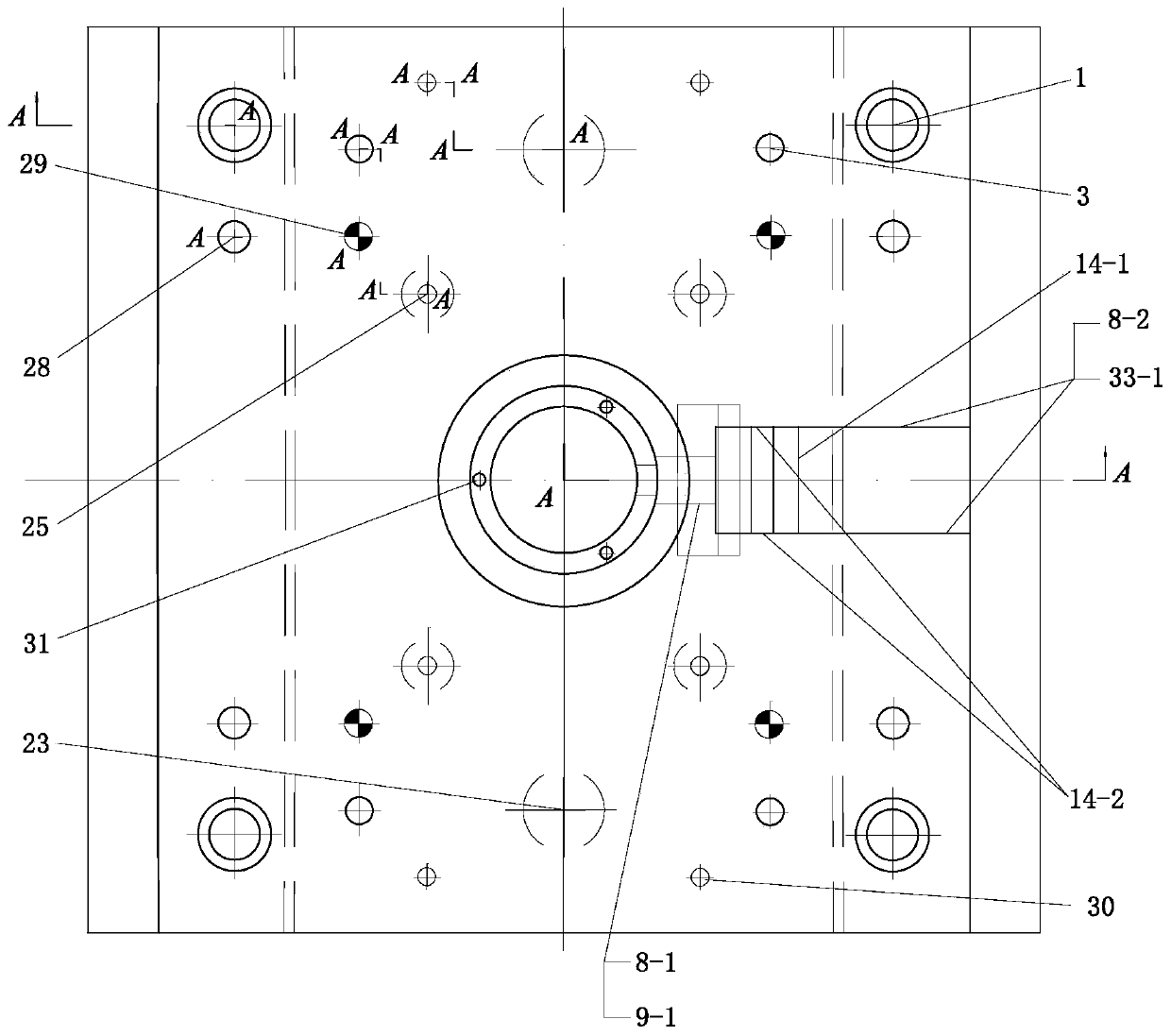
[0044] The lateral core-pulling mechanism of inclined plane pushing and reset proposed by the present invention is as follows: Figure 1-2 shown (where, figure 2It mainly reflects the distribution position of core cavity, inclined push block, lateral core, lateral plate, connecting rod, push rod, reset rod, push plate guide post, guide post, hexagon socket screw, ejector rod of injection machine, etc. ), including formwork, wedge blocks, lateral cores, lateral plates, inclined push blocks, two-stage sequential push-out...


PUM


Abstract

The invention discloses a lateral core-pulling mechanism capable of pushing and returning on an oblique plane and a method. The lateral core-pulling mechanism is equipped with two-stage sequential pushing-out mechanisms, so that actions of opening a mould, pulling a core, de-moulding a plastic part, firstly returning the pushing-out mechanisms, closing the mould and returning and locking a lateralmould core are sequentially performed. The pushing-out mechanisms disclosed by the invention realize a core-pulling function; while pushed out, oblique plane inclined blocks mounted on the pushing-out mechanisms push a lateral plate in an inclined mode, so that pulling-out of the lateral mould core is accomplished; a wedging block realizes returning of the core-pulling mechanism, so that during mould closing, the wedging block mounted on a fixed mould part is in contact with the inclined surface of the lateral plate, and therefore, returning and locking of the lateral mould core are realized;the lateral mould core mounted and fixed on the lateral plate is in clearance fit to a hole formed in a corresponding mould cavity plate, and positions, which correspond to the lateral plate, of themould are reserved with spaces capable of allowing the lateral plate to move, so that motion guide and limitation of the core-pulling mechanism is realized; and the actions of opening the mould, pulling the core, de-moulding the plastic part, firstly returning the pushing-out mechanisms, closing the mould, returning and locking the lateral mould core, and the like are sequentially performed.

Description

technical field [0001] The invention relates to a lateral core-pulling mechanism, in particular to a lateral core-pulling mechanism and a lateral core-pulling method for pushing and resetting on an inclined plane, and belongs to the technical field of molds. Background technique [0002] When injection molding plastic parts with holes, recesses, bosses and other shapes on the side, the parts molded on the mold are generally designed to be able to move sideways, so that the sideways can be pulled out before the plastic parts are demoulded. Molded parts, otherwise the plastic parts may not be demolded, so it is necessary to design a mechanism that drives the laterally formed parts to move laterally (drawing and resetting), that is, the lateral core-pulling mechanism. [0003] According to different power sources, the existing lateral core-pulling mechanisms are divided into three categories: manual core-pulling, motorized core-pulling, and hydraulic (or pneumatic) core-pulling...

Claims


Application Information

Patent Timeline
Patent Type & Authority Applications(China)
IPC IPC(8): B29C45/33B29C45/66
CPCB29C45/332B29C45/66
Inventor 江昌勇江妦李丹虹姜伯军
Owner CHANGZHOU INST OF TECH
Learn More