
Laser guiding system capable of achieving suspension driving on machine tool movement part

A technology of moving parts and suspension drive, which is applied in the direction of metal processing machinery parts, manufacturing tools, measuring/indicating equipment, etc. It can solve problems such as deformation, thermal deformation, and processing errors, and achieve the effect of high-precision linear motion

Inactive Publication Date: 2017-08-11
TSINGHUA UNIV
View PDF5 Cites 0 Cited by
  • Summary
  • Abstract
  • Description
  • Claims
  • Application Information

AI Technical Summary

Problems solved by technology

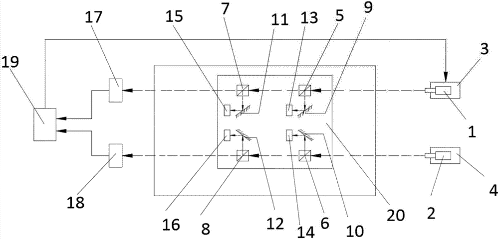
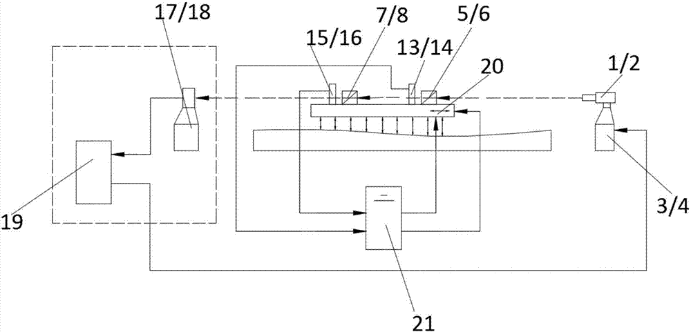
[0002] In the field of mechanical processing, the motion error caused by the deformation of the mechanical guide rail of the machine tool often affects the machining accuracy, and the mechanical guide rail is often affected by mechanical deformation, thermal deformation, and processing errors. It is mature and provides the possibility of non-contact support between the moving parts and the mechanical guide rail of the machine tool, so that the trajectory of the moving part no longer depends on the mechanical guide rail. Through the investigation of existing patents, it is found that there is no laser guide rail for the machine tool moving parts. The laser guidance system of suspension drive guidance and control, using the characteristics of laser collimation, combined with the suspension technology adopting active control strategy, provides convenience and possibility for the information guidance of the suspension parts of the machine tool

Method used


Image

  • Laser guiding system capable of achieving suspension driving on machine tool movement part
  • Laser guiding system capable of achieving suspension driving on machine tool movement part

Examples


Embodiment Construction

[0012] The following will clearly and completely describe the technical solutions in the embodiments of the present invention with reference to the accompanying drawings in the embodiments of the present invention. Obviously, the described embodiments are only some, not all, embodiments of the present invention. Based on the embodiments of the present invention, all other embodiments obtained by persons of ordinary skill in the art without making creative efforts belong to the protection scope of the present invention.

[0013] see Figure 1-2 , the present invention provides a technical solution: a laser guidance system driven by the suspension of moving parts of a machine tool, including No. 1 laser 1, No. 2 laser 2 and moving parts 20, and the No. 1 laser 1 and No. There is a No. 1 laser fine-tuning device 3 and a No. 2 laser fine-tuning device 4. A No. 1 optical receiver 17 is arranged in the laser emitting direction of the No. 1 laser. The input end of the No. 1 optical r...


PUM


Abstract

The invention discloses a laser guiding system capable of achieving suspension driving on a machine tool movement part. The laser guiding system comprises two lasers, two laser fine-adjusting devices, four light splitting devices, four optical sensors, an optical guide rail control unit, an information guiding control system and the movement part. According to the laser guiding system, two laser guide rails generated by the two lasers achieve transmission and reflection through the two-stage light splitting devices, the optical guide rail control unit receives transmission light rays and controls the laser fine-adjusting devices to adjust the spatial angles and displacement of the two lasers, and then the two laser guide rails meet the system guiding precision requirements; reflection light rays are parallel to the laser guide rails and are received by the four optical sensors, the information guiding control system achieves movement guiding of the laser guide rails on the movement part by controlling feeding movement and the suspension height of the movement part without being influenced by mechanical deformation, thermal deformation, machining errors and the like of a mechanical supporting part of a machine tool, and then high-precision linear movement of the movement part is achieved.

Description

technical field [0001] The invention relates to the technical field of mechanical manufacturing, in particular to a laser guidance system for suspension driving of machine tool moving parts. Background technique [0002] In the field of mechanical processing, the motion error caused by the deformation of the mechanical guide rail of the machine tool often affects the machining accuracy, and the mechanical guide rail is often affected by mechanical deformation, thermal deformation, and processing errors. It is mature and provides the possibility of non-contact support between the moving parts and the mechanical guide rail of the machine tool, so that the trajectory of the moving part no longer depends on the mechanical guide rail. Through the investigation of existing patents, it is found that there is no laser guide rail for the machine tool moving parts. The laser guidance system of suspension drive guidance and control, using the characteristics of laser collimation, combi...

Claims


Application Information

Patent Timeline
Patent Type & Authority Applications(China)
IPC IPC(8): B23Q17/24
CPCB23Q17/2414
Inventor 周凯李雅哲吕江伟荣海
Owner TSINGHUA UNIV
Learn More