Pre-amplifier, MEMS sensor readout circuit, and MEMS sensor system
A technology of preamplifier and readout circuit, which is applied in the direction of improving amplifiers to improve efficiency, improving amplifiers to reduce noise impact, amplifiers, etc. It can solve the problems that MEMS sensor systems cannot meet the requirements of low power consumption and low noise at the same time, and achieve Low power consumption requirements, power consumption reduction, low noise elimination effect
- Summary
- Abstract
- Description
- Claims
- Application Information
AI Technical Summary
Problems solved by technology
Method used
Image

Examples
Embodiment 1
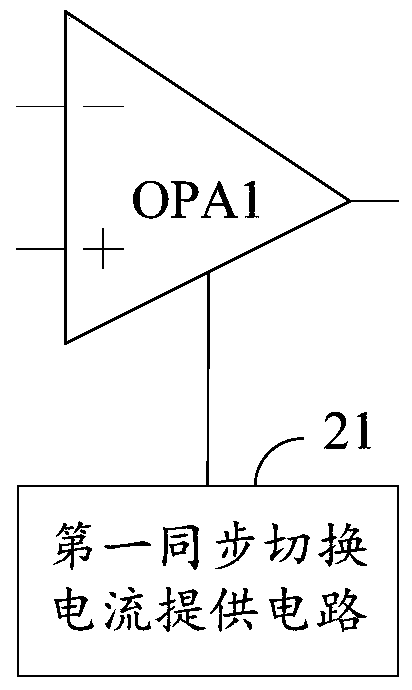
[0060] This embodiment provides a preamplifier, which is applied to a MEMS sensor readout circuit. figure 2 It is a partial structural schematic diagram of the preamplifier, the preamplifier includes a first operational amplifier OPA1 and a first synchronous switching current supply circuit 21, and the first operational amplifier OPA1 includes a first bias circuit and amplifier circuits of various stages . The number of stages of the amplifying circuit is generally three stages, namely, an input-stage amplifying circuit, an output-stage amplifying circuit, and an intermediate-stage amplifying circuit. The number of stages of the amplification circuit is set according to actual requirements, which is not limited in this embodiment. Further, besides the first bias circuit and amplifier circuits of various stages, the first operational amplifier OPA1 may also be provided with some functional circuits, such as protection circuits, etc. according to actual needs. The preamplifie...
Embodiment 2
[0082] In some application scenarios, the phase of the first operational amplifier OPA1 needs to be compensated. Therefore, this embodiment provides a preamplifier. Compared with the preamplifier provided in Embodiment 1, the difference is that: the preamplifier further includes a phase compensation unit, and the phase compensation unit is used to compensate the phase margin, ensuring the stability of the first operational amplifier OPA1. Figure 5is a schematic diagram of the circuit structure of the preamplifier, and the phase compensation unit includes an eighth switch K48 and a compensation capacitor C42. One end of the eighth switch K48 is connected to the output end of the first operational amplifier OPA1, the other end of the eighth switch K48 is connected to one end of the compensation capacitor C42, and the control end of the eighth switch K48 is used to receive For the second control signal S42, the other end of the compensation capacitor C42 is grounded. When the ...
Embodiment 3
[0084] This embodiment provides a preamplifier, Image 6 It is a schematic diagram of the circuit structure of the preamplifier. Compared with the preamplifier provided in Embodiment 1, the difference is that the preamplifier also includes a ninth switch K49. The inverting input terminal of the first operational amplifier OPA1, one terminal of the fifth switch K45 and one terminal of the feedback capacitor C41 are connected to the middle electrode of the MEMS sensor 40 through the ninth switch K49, and the ninth switch K49 is connected to the middle electrode of the MEMS sensor 40. The control terminal of the switch K49 is used for receiving the first control signal S41. By setting the ninth switch K49, when the readout circuit is working in the clearing phase, the first control signal S41 controls the ninth switch K49 to be turned off, thereby disconnecting the preamplifier from the The connection of the MEMS sensor 40 is not affected by the signal change of the MEMS sensor ...
PUM
 Abstract
Description
Claims
Application Information
 - R&D
- Intellectual Property
- Life Sciences
- Materials
- Tech Scout
- Unparalleled Data Quality
- Higher Quality Content
- 60% Fewer Hallucinations
Browse by: Latest US Patents, China's latest patents, Technical Efficacy Thesaurus, Application Domain, Technology Topic, Popular Technical Reports.
© 2025 PatSnap. All rights reserved.Legal|Privacy policy|Modern Slavery Act Transparency Statement|Sitemap|About US| Contact US: help@patsnap.com