A method for testing low-frequency voltage/current fluctuation parameters of solar cell modules
A solar cell, low-frequency voltage technology, applied in the monitoring of electrical components, photovoltaic power generation, photovoltaic systems, etc., can solve the problems of single test mode and unsatisfactory test results, achieve accurate test collection, ensure accuracy and reliability Effect
- Summary
- Abstract
- Description
- Claims
- Application Information
AI Technical Summary
Problems solved by technology
Method used
Image
Examples
Embodiment 1
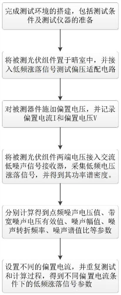
[0088] Forward bias low frequency voltage / current fluctuation signal test process, such as figure 1 Shown:
[0089] Step 1 After the test environment is set up, place the ground-use crystalline silicon photovoltaic cell module (maximum power 330W, open circuit voltage 45.1V, short circuit current 9.45A, maximum power point voltage 37.2V, maximum power point current 8.87A) in a shielded dark room , and ensure that there is no electromagnetic interference during the test.
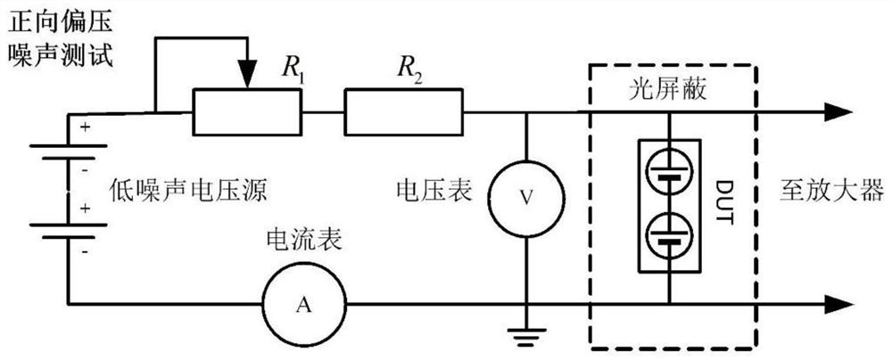
[0090] Step 2 Connect the photovoltaic module under test to the forward bias low-frequency fluctuation signal test adaptation circuit. The positive voltage output terminal of the photovoltaic module is connected to the positive power supply terminal of the adapter through isolation and adjustment resistance, and the negative voltage output terminal of the photovoltaic module is connected to the Adapter negative power supply terminal, the adapter circuit such as figure 2 shown.
[0091] Step 3 Apply a forw...
Embodiment 2
[0098] Reverse bias low frequency voltage / current fluctuation signal test:
[0099] Step 1 Place the crystalline silicon photovoltaic cell module to be tested (maximum power 330W, open circuit voltage 45.1V, short circuit current 9.45A, maximum power point voltage 37.2V, maximum power point current 8.87A) in a shielded dark room, and ensure that the test The process is free from electromagnetic interference, such as figure 1 Shown:
[0100] Step 2 Connect the photovoltaic module under test to the reverse bias low-frequency voltage / current fluctuation signal test adaptation circuit. The negative voltage output terminal of the photovoltaic module is connected to the positive power supply terminal of the adapter through isolation and adjustment resistance, and the positive voltage output terminal of the photovoltaic module is The end is connected to the negative power supply end of the adapter, the adapter circuit such as image 3 shown.
[0101] Step 3 Apply a reverse bias vo...
PUM
 Abstract
Description
Claims
Application Information
 - R&D
- Intellectual Property
- Life Sciences
- Materials
- Tech Scout
- Unparalleled Data Quality
- Higher Quality Content
- 60% Fewer Hallucinations
Browse by: Latest US Patents, China's latest patents, Technical Efficacy Thesaurus, Application Domain, Technology Topic, Popular Technical Reports.
© 2025 PatSnap. All rights reserved.Legal|Privacy policy|Modern Slavery Act Transparency Statement|Sitemap|About US| Contact US: help@patsnap.com


