
Fuel cell metal electrode plate and forming method

A metal plate and fuel cell technology, applied in fuel cells, fuel cell components, circuits, etc., can solve problems such as inability to communicate with each other, coolant diffusion, uneven diffusion, etc., to increase reaction efficiency and ensure output power , to ensure the effect of reaction efficiency

Pending Publication Date: 2019-10-25
苏州治臻新能源装备有限公司
View PDF0 Cites 4 Cited by
  • Summary
  • Abstract
  • Description
  • Claims
  • Application Information

AI Technical Summary

Problems solved by technology

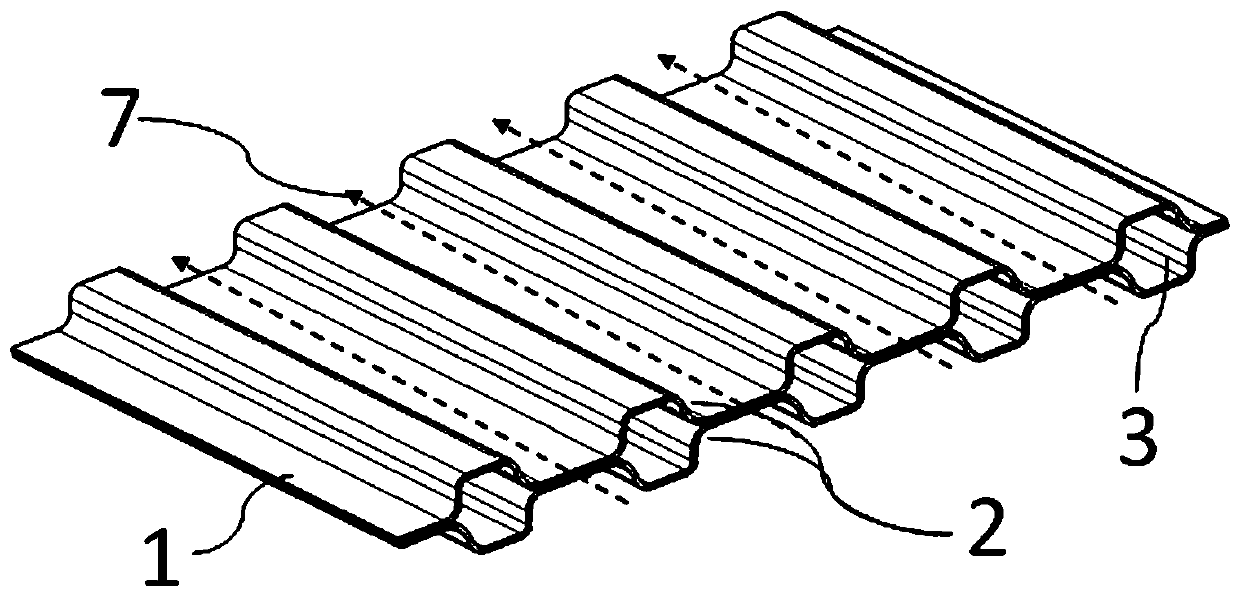
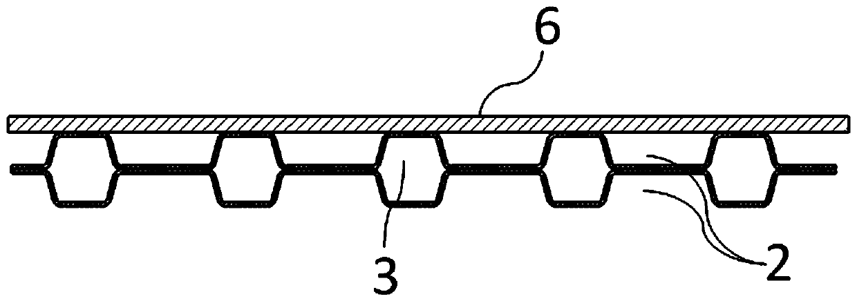
[0006] However, in a traditional metal plate fuel cell, because the groove structures are distributed parallel to each other, after covering the upper membrane electrode 6, the adjacent gas flow channels 2 are separated from each other by the ridge structure, resulting in a First, only half of the area of ​​the membrane electrode 6 is covered on the groove structure, which can contact with the gas flowing in the gas flow channel 2, participate in electron exchange, and reduce the reaction area of ​​the fuel cell; secondly, because each liquid flow channel 3 is also If they are not connected to each other, the coolant cannot diffuse to the area where the gas flow channel 2 is located, and can only cool the gas flow channel 2 from the side, reducing the effective cooling area and resulting in low cooling efficiency
[0007] Because the metal plate 1, including the gas flow channels 2 therein, is usually integrally formed by stamping, the gas flow channels 2 are usually isolated from each other, so that the reaction gas cannot flow between the separated gas flow channels 2. Mutual circulation, so the reaction gas is diffused unevenly in the overall reaction area of ​​the metal plate 1, which reduces the reaction efficiency of the reaction gas
The uneven distribution of the cooling liquid may cause large temperature changes between the various local areas of the membrane electrode 6, which will affect the reaction efficiency of the membrane electrode 6, and then reduce the output power of the fuel cell.

Method used


Image

  • Fuel cell metal electrode plate and forming method
  • Fuel cell metal electrode plate and forming method
  • Fuel cell metal electrode plate and forming method

Examples


Embodiment Construction

[0037] The present invention provides a fuel cell metal pole plate and its forming method. In order to make the purpose, technical solution and effect of the present invention clearer and clearer, the present invention will be further described in detail below with reference to the accompanying drawings and examples. It should be understood that the specific embodiments described here are only used to explain the present invention, not to limit the present invention.

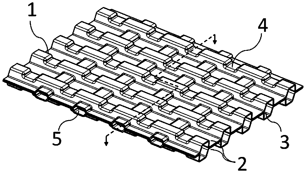
[0038] Similar to the metal pole plate of the prior art, the fuel cell metal pole plate 1 provided by the present invention is as image 3As shown, it also includes two unipolar plates that are bonded back to each other, i.e., the cathode unipolar plate and the anode unipolar plate, which are respectively electrically connected to the anode and the cathode on the inner membrane electrode 6 of the nearest fuel cell, so that the Each fuel cell unit is connected in series to form a fuel cell that outputs sufficient...


PUM


Abstract

The invention provides a fuel cell metal electrode plate and a forming method. Through the arrangement of a group of gas flow channels which are communicated with each other and a group of liquid flowchannels which are communicated with each other, reaction gas can be uniformly diffused into all the gas flow channels when flowing through the gas flow channels, thereby improving and guaranteeing the uniform contact with a membrane electrode, and improving the reaction efficiency of the fuel cell; moreover, when cooling liquid flows through the liquid flow channels, the cooling liquid is distributed more uniformly through mutual communication and diffusion, so that a membrane electrode is cooled more uniformly, large temperature change of a local part of the membrane electrode can be avoided, the reaction efficiency of the membrane electrode is further ensured, and the output power of a fuel cell is further ensured.

Description

technical field [0001] The invention relates to the field of fuel cells, in particular to a fuel cell metal pole plate and a forming method. Background technique [0002] Fuel cell, currently under development, mainly refers to proton exchange membrane fuel cell (PEMFC), which uses hydrogen-rich gas such as natural gas as fuel, and is a device that directly converts the chemical energy of fuel into electrical energy. Usually, the electrochemical reaction occurs directly through hydrogen and oxygen to output electric energy, and the product of the reaction is water, which basically achieves zero emission. [0003] The structure of the fuel cell is simple, and the core components are membrane electrodes and bipolar plates. Membrane electrodes consist of a proton-conducting membrane and electrodes (cathode and anode) arranged on both sides of the membrane. The function of the bipolar plate (also known as the separator) is to provide gas flow channels, prevent the hydrogen and...

Claims


Application Information

Patent Timeline
Patent Type & Authority Applications(China)
IPC IPC(8): H01M8/0206H01M8/0258H01M8/0267
CPCH01M8/0206H01M8/0258H01M8/0267Y02E60/50Y02P70/50
Inventor 王凯姜天豪徐一凡毕飞飞彭林法蓝树槐
Owner 苏州治臻新能源装备有限公司
Learn More