Winching potential energy real-time recycling system and control method thereof

A potential energy recovery and potential energy technology, applied in the field of hoist hydraulics, can solve problems such as restricting application, inconvenient construction machinery structure design, and difficulty in hoisting down at a constant speed, achieving obvious energy-saving effect, simple and reliable pipeline connection, and excellent energy-saving effect. Effect

Pending Publication Date: 2019-10-25
SUNWARD INTELLIGENT EQUIP CO LTD
View PDF6 Cites 8 Cited by
  • Summary
  • Abstract
  • Description
  • Claims
  • Application Information

AI Technical Summary

Problems solved by technology

[0008] In the energy recovery system in the form of hydraulic energy storage, when the recovered energy is large, the working volume of the accumulator will be very large, which is not convenient for the structural design of construction machinery, and the pressure in the accumulator will increase with the charging. The increase of the oil entering the system makes it difficult to control the lowering of the winch at a constant speed. Therefore, this system does not solve the two difficulties in the energy-saving control of the main winch system.
[0009] In the energy recovery system stored in the form of electric energy, there are many up-conversion links in the way of energy recovery and utilization, and the system structure is complex and difficult to control. When recovering huge energy, it is necessary to use supercapacitors with high energy density and small footprint for energy storage. However, at present, supercapacitors are expensive, and do not meet the economical requirements of the difficulties in the energy-saving control of the main winch system, which restricts their application in practical engineering.

Method used


Image

  • Winching potential energy real-time recycling system and control method thereof
  • Winching potential energy real-time recycling system and control method thereof
  • Winching potential energy real-time recycling system and control method thereof

Examples


Embodiment

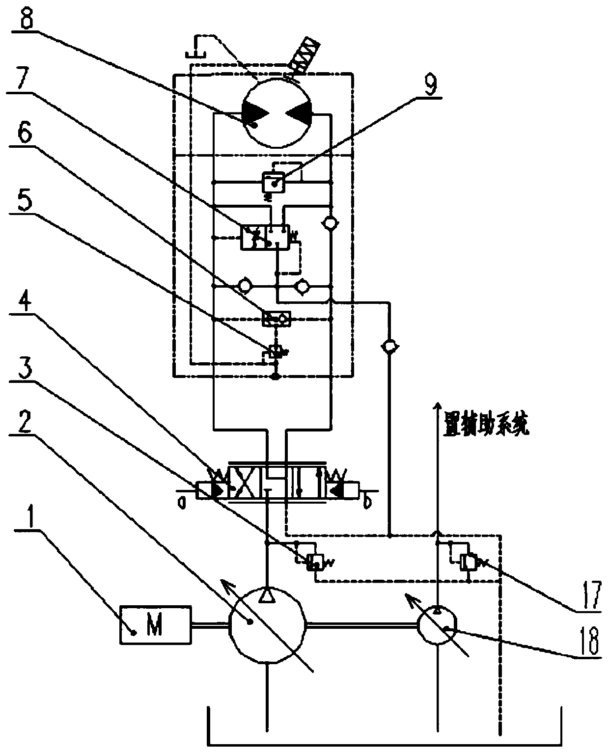
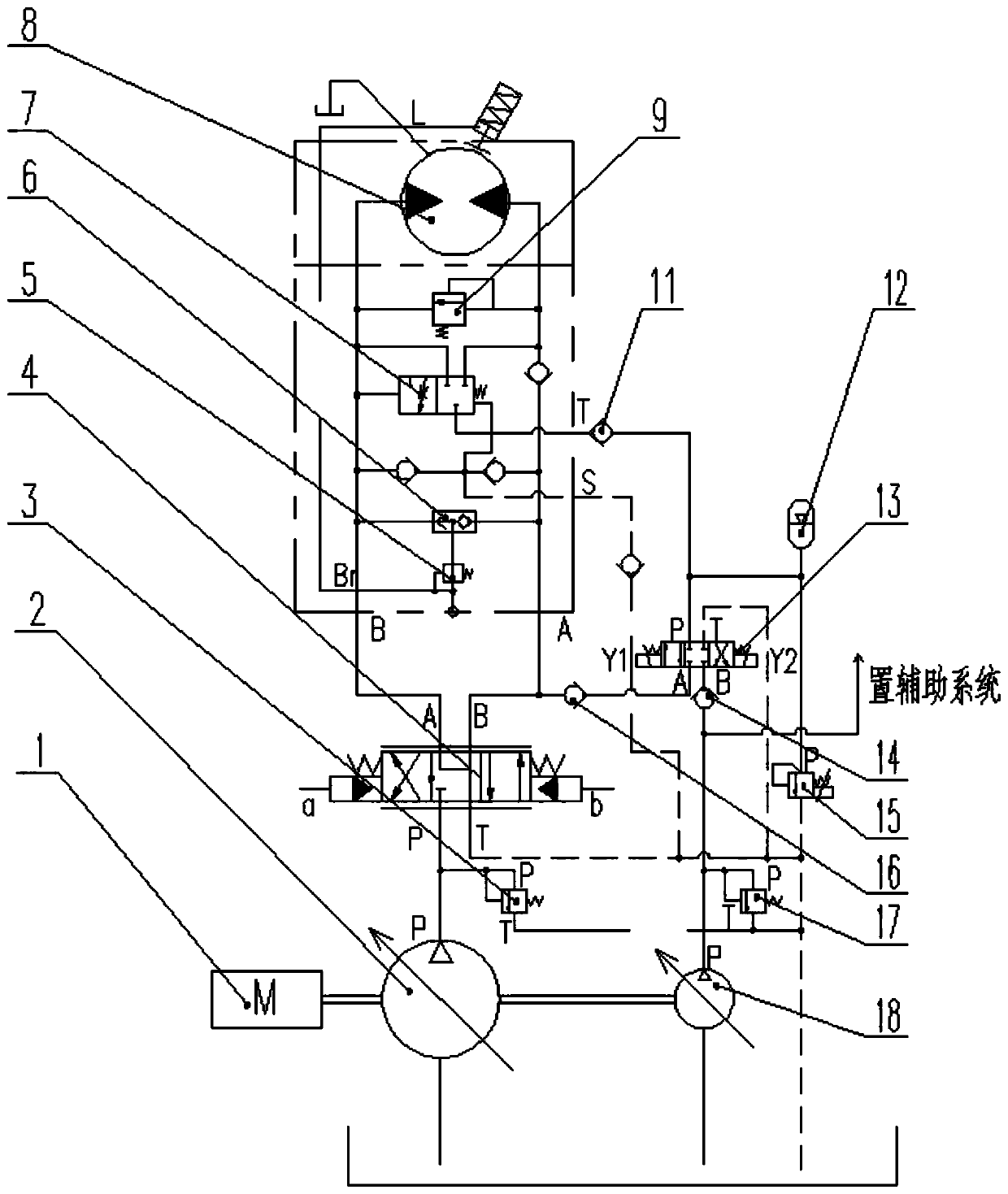
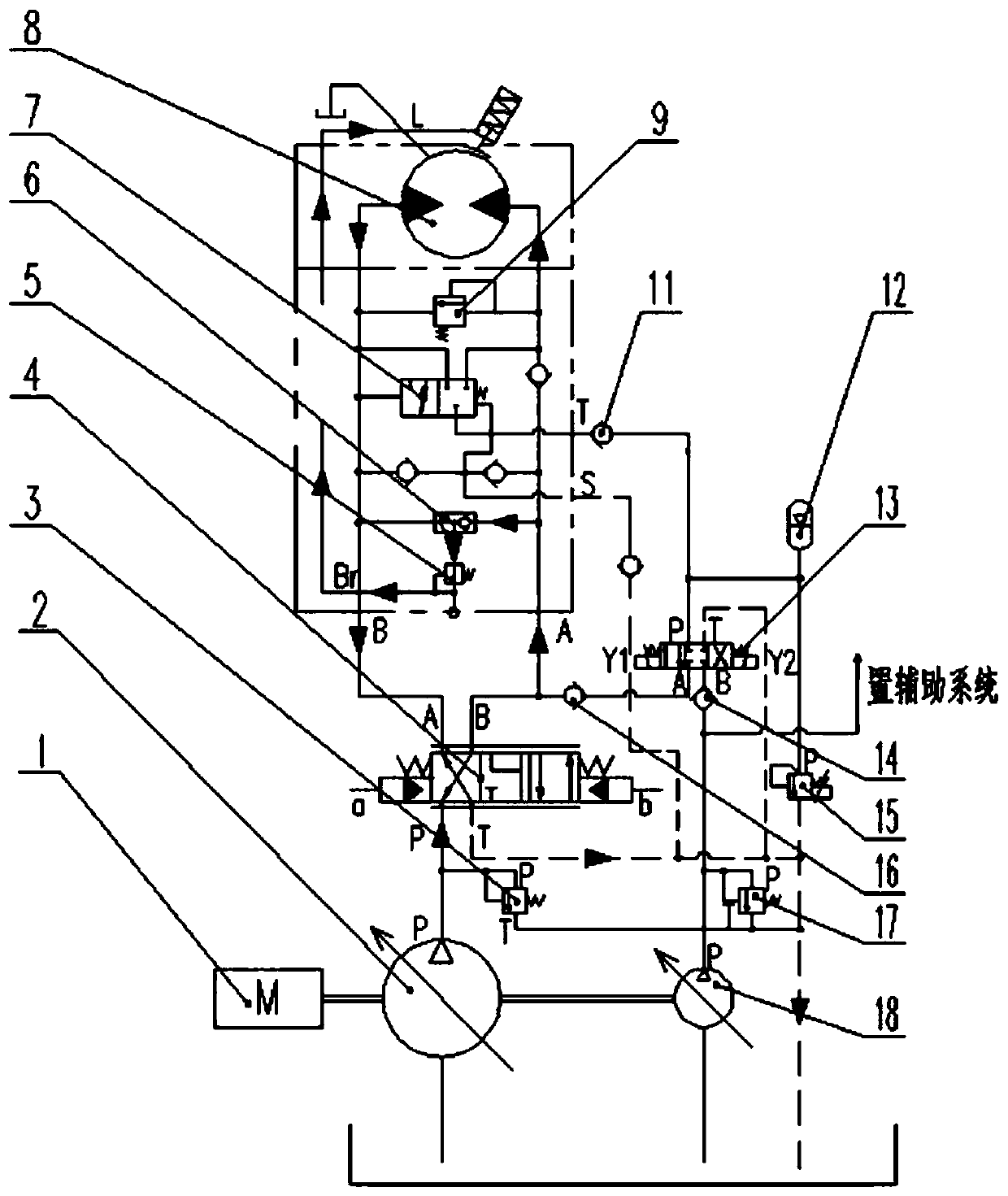
[0042] see figure 2 , the hoisting potential energy real-time recovery and utilization system in the illustration is a specific embodiment of the present invention, including an engine 1, a main pump 2, a main pump overflow valve 3, a reversing main valve 4, a pressure reducing valve 5, a shuttle valve 6, Pilot balance valve 7, winch motor 8, overload protection valve 9, check valve 11 / 13 / 16, accumulator 12, potential energy recovery reversing valve 13, electric proportional relief valve 15, auxiliary pump relief valve 17 And auxiliary pump 18.

[0043] Among them, the main pump 2 and the auxiliary pump 18 are coaxially driven by the engine 1. The coaxial referred to here refers to the synchronous transmission of the main pump 2 and the auxiliary pump 18 through the output shaft of the engine 1, wherein the main pump 2 controls the winch motor 8 The auxiliary pump 18 is used as other hydraulic auxiliary system to provide pressure oil. The main pump 2 and the auxiliary pump 1...


PUM


Abstract

The invention discloses a winching potential energy real-time recycling system and a control method thereof. The winching potential energy real-time recycling system comprises a main pump, an auxiliary pump, a reversing main valve, a potential energy recovery reversing valve and a balancing valve set. The main pump is connected to an oil inlet passage and an oil outlet passage of a winch motor through the reversing main valve, and the balancing valve set is arranged between the oil inlet passage and the oil outlet passage of the winch motor. An oil return passage is guided out of a balancing valve outlet of the balancing valve set, and the oil return passage is connected with an oil return opening of the reversing main valve and a pressure oil opening of the auxiliary pump through the potential energy recovery reversing valve. A secondary element pump/motor in coaxial transmission with the main pump is adopted by the auxiliary pump. According to the winching potential energy real-timerecycling system and the control method thereof, the potential energy of load devolution is recycled in real time at the winch stable devolution stage, so that an engine for driving the main pump works in the state of zero power or low-power output; real-time recycling of the winching potential energy is achieved, and an excellent energy saving effect is achieved; and the winching potential energyreal-time recycling system is especially suitable for an engineering machine hydraulic system for driving multiple pumps through a single engine, and the cost of the hydraulic system does not need tobe increased too much.

Description

technical field [0001] The invention belongs to the winch hydraulic technology, in particular to a winch potential energy real-time recovery and utilization system and a control method thereof. Background technique [0002] Most of the construction machinery is equipped with high-power internal combustion engines, which have high fuel consumption and huge volume of exhaust emissions. Therefore, the pollution of the exhaust emissions to the air is also in an increasingly non-negligible position. Based on the two aspects of national energy security and air pollution control It is urgent to strengthen the research on energy-saving control technology of construction machinery and vigorously promote the application of energy-saving technology. The winch system of construction machinery is mainly used for lifting and lowering heavy objects. At present, during the lowering process of the winch system, not only the gravitational potential energy released by the weight itself is lost...

Claims


Application Information

Patent Timeline
Patent Type & Authority Applications(China)
IPC IPC(8): F15B1/02F15B11/08F15B13/02F15B21/14B66D1/08
CPCF15B1/024F15B11/08F15B13/02F15B13/027F15B21/14B66D1/08B66D2700/0133F15B2211/20576F15B2211/212F15B2211/88
Inventor 朱振新曾素张奇志罗钊
Owner SUNWARD INTELLIGENT EQUIP CO LTD
Why Eureka
Try Eureka