Engine brake device

A technology of engine braking and rocker shaft, which is applied in the direction of engine components, machines/engines, valve devices, etc., can solve the problems of unstable transient transition process of the engine, long time of intervention and exit, etc., and achieve oil demand and The oil supply capacity of the oil pump is reduced, the entry and exit time is shortened, and the effect of increasing the use area

Pending Publication Date: 2019-10-25
ZHEJIANG LIMING INTELLIGENT MFG CO LTD
View PDF3 Cites 0 Cited by
  • Summary
  • Abstract
  • Description
  • Claims
  • Application Information

AI Technical Summary

Problems solved by technology

Another example is the use of oil-driven engine braking. The time for engine braking to enter and exit is generally longer (>0.4s), which will affect the transition process of engine braking and ignition states, resulting in unstable transient transition process of the engine.

Method used


Image

  • Engine brake device
  • Engine brake device
  • Engine brake device

Examples


Embodiment Construction

[0057] Embodiments of the present invention will be further described below in conjunction with accompanying drawings:

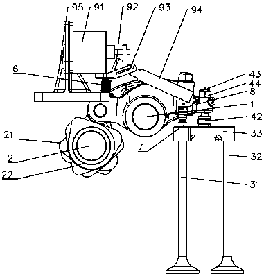
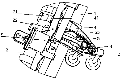
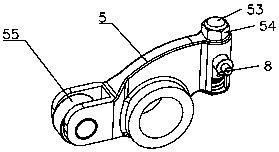
[0058] Such as Figure 1-2 As shown, an engine braking device includes a rocker shaft 1, a camshaft 2, an exhaust valve 3, an exhaust rocker 4, an auxiliary rocker 5, an elastic element 6, a sliding pin 7, a control mechanism 8, an electric drive Institution 9.

[0059] The rocker shaft 1 is arranged parallel to the camshaft 2, and the camshaft 2 has an exhaust cam 21 and an auxiliary cam 22 arranged adjacently, and the rotation of the camshaft 2 can simultaneously drive the exhaust cam 21 and the auxiliary cam 22 rotate.

[0060] The exhaust valve 3 includes a first exhaust valve 31, a second exhaust valve 32, and a valve bridge 33 horizontally arranged on the first exhaust valve 31 and the second exhaust valve 32, the first exhaust valve 31 and the second exhaust valve 32 The second exhaust valves 32 are mushroom-shaped valves, which are used to control...


PUM


Abstract

The invention relates to an engine brake device. The engine brake device is characterized by comprising a control mechanism and an electric drive mechanism; the control mechanism comprises a housing,a first limiting member, a first elastic member, an execution plunger, a second limiting member, a second elastic member and a transfer plunger; the execution plunger has a first position where the transfer plunger is locked and a second position where the transfer plunger is not locked, the electric drive mechanism includes an execution motor, a slide plate frame, a slide plate and a contact leafspring, the execution motor can push the slide plate to slide along the slide plate frame, and the contact leaf spring is driven to push the execution plunger to slide and enable the execution plunger to keep at the first position. The engine brake device has the advantages that the electric drive mechanism and the control mechanism are arranged, the execution motor controls action, the manner ofusing engine oil as a working or driving control medium is replaced, the reliability risk brought by the engine oil is eliminated, the engine brake use area is increased, the engine brake starting and stopping time is shortened, the fuel consumption is reduced, and engine braking performance classification is more detailed.

Description

technical field [0001] The invention relates to a medium-heavy diesel and natural gas engine, in particular to an engine braking device. Background technique [0002] There are many mountains in our country, and the mountain area is vast, accounting for about 69% of the total land area. When heavy trucks travel on long downhill roads in mountainous areas, drivers frequently use the service brake. The service brake can absorb a large amount of energy in a short period of time. As the time increases, the surface temperature of the friction pair between the brake drum and the brake shoe will increase, and the friction coefficient will decrease, which will eventually lead to a dangerous situation of reduced braking performance or even brake failure, causing major traffic accidents. In order to improve the driving safety of heavy-duty commercial vehicles, it is necessary to add an auxiliary braking system on the basis of service braking to ensure that the vehicle has a constant b...

Claims


Application Information

Patent Timeline
Patent Type & Authority Applications(China)
IPC IPC(8): F01L13/06F01L9/04F01M9/10F01L9/22
CPCF01L13/06F01M9/10F01L9/20
Inventor 俞黎明俞振寰
Owner ZHEJIANG LIMING INTELLIGENT MFG CO LTD
Why Eureka
Try Eureka