
Particle counting and packaging machine

A packaging machine and counting technology, applied in packaging, packaging protection, transportation and packaging, etc., can solve problems such as difficult to control distance, product quantity error, and affect product quality, so as to achieve a wide range of applications, avoid friction damage, and guarantee The effect of product quality

Pending Publication Date: 2019-10-25
东莞市焦大自动化科技有限公司
View PDF9 Cites 2 Cited by
  • Summary
  • Abstract
  • Description
  • Claims
  • Application Information

AI Technical Summary

Problems solved by technology

[0003] However, the above-mentioned existing equipment still has the following deficiencies in use; first, there are certain limitations in the way of feeding through the vibrating feeding tray. On the one hand, the feeding of the vibrating feeding tray can only be used for some smaller Work with lighter products. Once the product quality or volume is large, it is impossible to use the vibrating feeding tray to work. On the other hand, when the vibrating feeding tray is working, the vibrating feeding tray itself does not move. The product is constantly moving inside. During the moving process, the product will rub against the vibrating feeding tray, which will easily cause product wear and affect the quality of the product.
Second, when the vibrating feeding tray is working, it is difficult to control the distance between two adjacent products, especially products with irregular shapes. Therefore, when counting and packaging, it is easy to cause errors in the number of products

Method used


Image

  • Particle counting and packaging machine
  • Particle counting and packaging machine
  • Particle counting and packaging machine

Examples


Embodiment Construction

[0025] The technical solutions of the present invention will be clearly and completely described below in conjunction with the accompanying drawings. Apparently, the described embodiments are some of the embodiments of the present invention, but not all of them.

[0026] The components of the embodiments of the invention generally described and shown in the figures herein may be arranged and designed in a variety of different configurations. Accordingly, the following detailed description of the embodiments of the invention provided in the accompanying drawings is not intended to limit the scope of the claimed invention, but merely represents selected embodiments of the invention.

[0027] Based on the embodiments of the present invention, all other embodiments obtained by persons of ordinary skill in the art without making creative efforts belong to the protection scope of the present invention.

[0028] In the description of the present invention, it should be noted that the...


PUM


Abstract

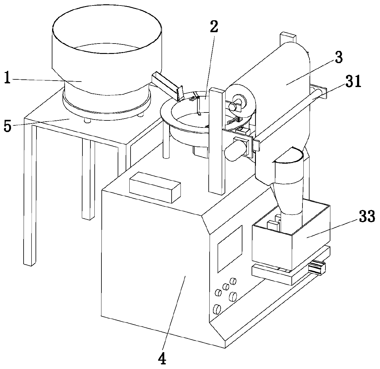
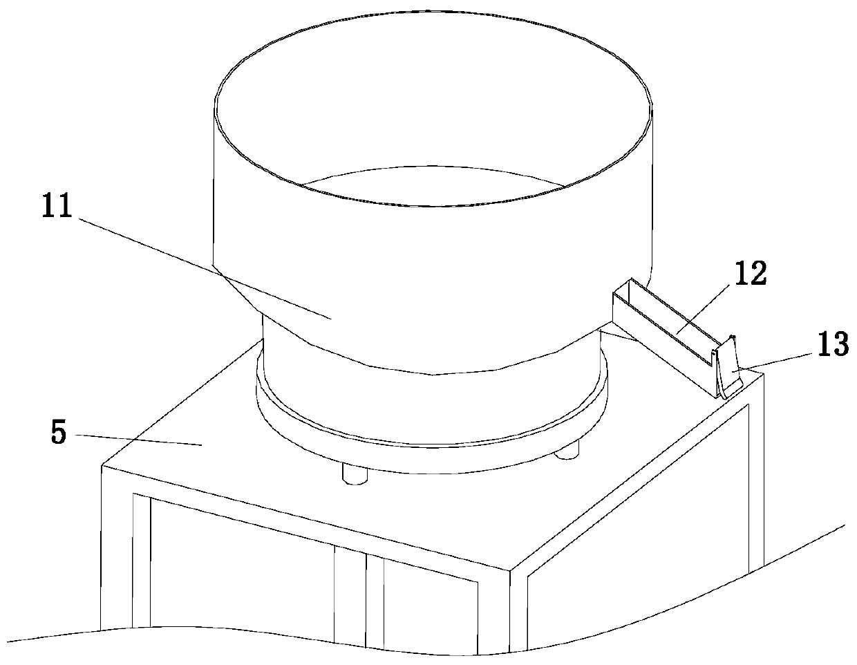
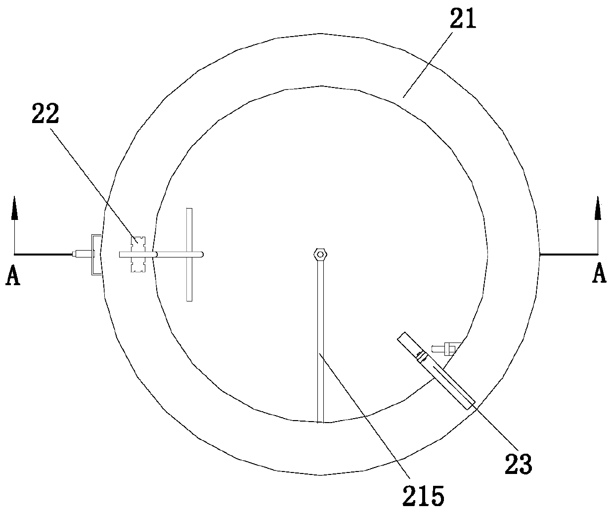
The invention discloses a particle counting and packaging machine, and belongs to the field of packaging machines. The particle counting and packaging machine comprises a feeding mechanism, a countingand discharging mechanism, a packaging mechanism and a power distribution cabinet, and the counting and discharging mechanism comprises a discharging component, a limiting component and a sensing component; the packaging mechanism comprises a discharging component, a traction component, a molding component, a first hot-pressing component and a second hot-pressing component, and the discharging component is arranged at the upper end of the power distribution cabinet; the molding component is located below the discharging component, and the first hot-pressing component is installed beside the molding component; and the second hot-pressing component is installed at the lower end of the molding component, and the traction component is arranged below the first hot-pressing component. Accordingto the particle counting and packaging machine, through arrangement of the discharging component, the wear of products in the discharging process can be reduced, so that the quality of the products is improved; the particle counting and packaging machine can be used for discharging the products with larger size and weight, and the limitation of the particle counting and packaging machine is reduced; the number of the products can be counted accurately in the discharging process, and the errors are reduced; and the particle counting and packaging machine is convenient and practical.

Description

technical field [0001] The invention relates to the field of packaging machine equipment, in particular to a particle count packaging machine. Background technique [0002] Packaging machine is a kind of commonly used mechanical equipment. Packaging machine is a machine for packaging products, which plays the role of protection and beauty. In the prior art, the packaging machine counts and packs the products through the cooperation of the vibrating feeding tray and the proximity switch when discharging, and the vibrating feeding tray transports the products inside it along the discharging channel in sequence through vibration When each product passes the proximity switch, it will trigger the proximity switch and make it generate an electrical signal to count. [0003] However, the above-mentioned existing equipment still has the following deficiencies in use; first, there are certain limitations in the way of feeding through the vibrating feeding tray. On the one hand, the ...

Claims


Application Information

Patent Timeline
IPC IPC(8): B65B1/08B65B37/16B65B57/20
CPCB65B1/08B65B37/16B65B57/20
Inventor 焦鹏凯邢仙鸽
Owner 东莞市焦大自动化科技有限公司
Learn More