
Preparation method and application of nano-catalyst for efficiently treating trimethylamine polluted gas

A nano-catalyst and polluting gas technology, applied in the direction of catalyst activation/preparation, physical/chemical process catalysts, chemical instruments and methods, etc., can solve problems such as performance impact, achieve the effect of removing trimethylamine and improving degradation effect

Active Publication Date: 2019-10-25
DALIAN UNIV OF TECH
View PDF4 Cites 5 Cited by
  • Summary
  • Abstract
  • Description
  • Claims
  • Application Information

AI Technical Summary

Problems solved by technology

However, in practical applications, due to the experimental conditions and methods, defects will inevitably appear in the molybdenum disulfide material, which has a very important impact on its performance.

Method used


Image

  • Preparation method and application of nano-catalyst for efficiently treating trimethylamine polluted gas
  • Preparation method and application of nano-catalyst for efficiently treating trimethylamine polluted gas
  • Preparation method and application of nano-catalyst for efficiently treating trimethylamine polluted gas

Examples


Embodiment 1

[0018] Example 1: Photoelectric coupled catalytic system removes trimethylamine

[0019] The above pretreated loads have Co-MoS 2 The conductive cathode of the catalyst is placed on one side of the membrane module, separated from the other side by a proton exchange membrane, and the anode side is placed at 0.5mol / L K 2 SO 4 Insert a copper rod into the electrolyte solution to form a corrosion metal cathode; put the assembled membrane module into the above stainless steel reactor, and use alligator clips to connect the two stages of copper wire and stainless steel mesh respectively, and the two poles are connected to the external resistance through wires to form a closed circuit. At the beginning of the experiment, trimethylamine aqueous solutions with different initial concentrations were injected from the inlet of the reactor, and a small fan fixed in the system was turned on before the reaction, so that the trimethylamine solution could be quickly volatilized and fully mix...

Embodiment 2

[0020] Example 2: Removal of trimethylamine by photoelectrocatalytic coupled microbial system

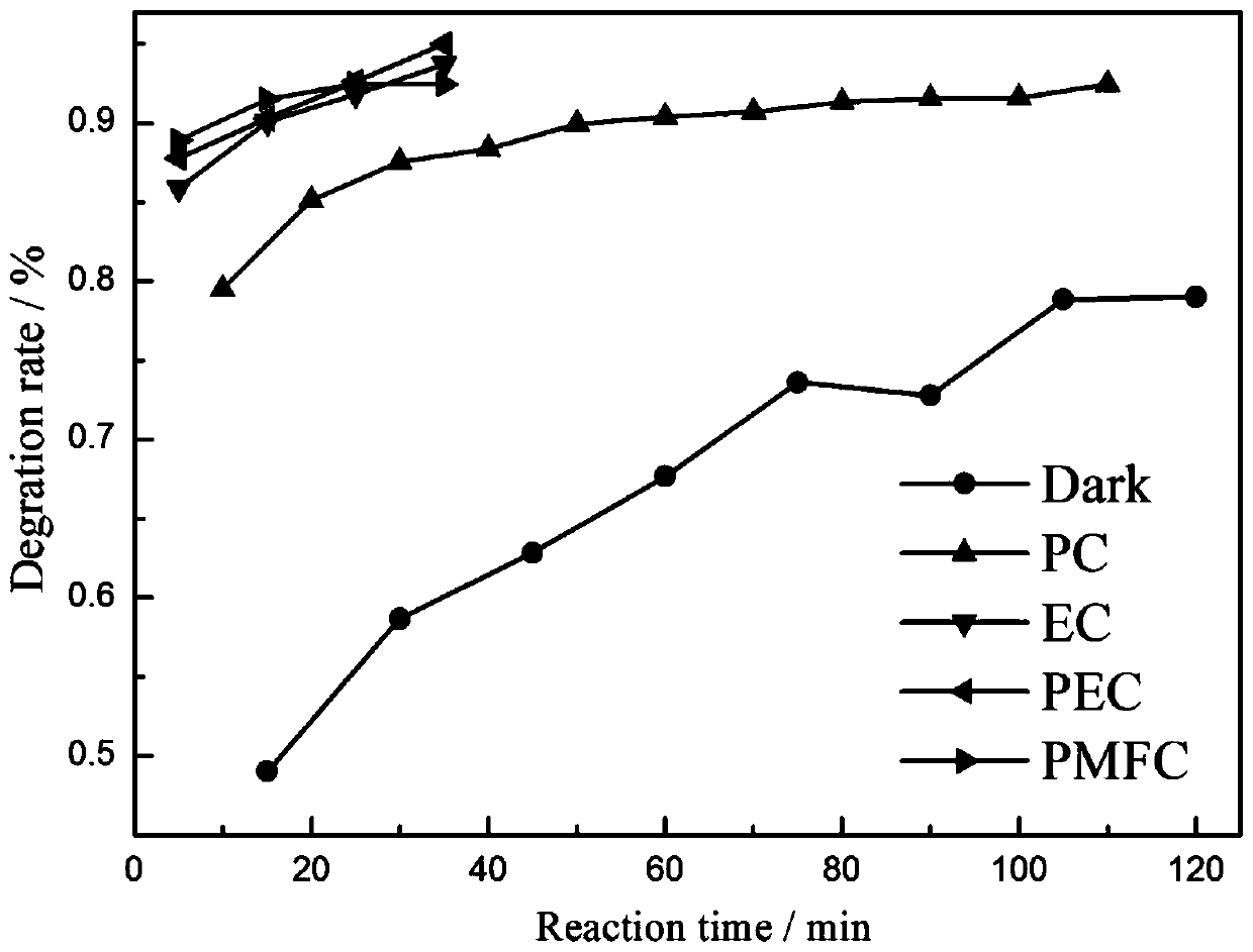
[0021] This system is essentially the same as the photoelectrocatalytic system that provides a bias voltage for metal corrosion and electricity generation. The difference is that in this system, the electricity-generating microorganism-Shewanella is used as the electricity-generating anode, and the microorganism attaches to and grows on carbon particles. On the above, the electrical energy generated by the microorganisms is exported through the inserted carbon rods, and the Co-MoS loaded 2 The conductive cathode of the catalyst forms a closed loop. Such as image 3 As shown, compared with the photocatalytic system, the efficiency of degrading trimethylamine in the photocoupled microbial system is basically the same.


PUM


Abstract

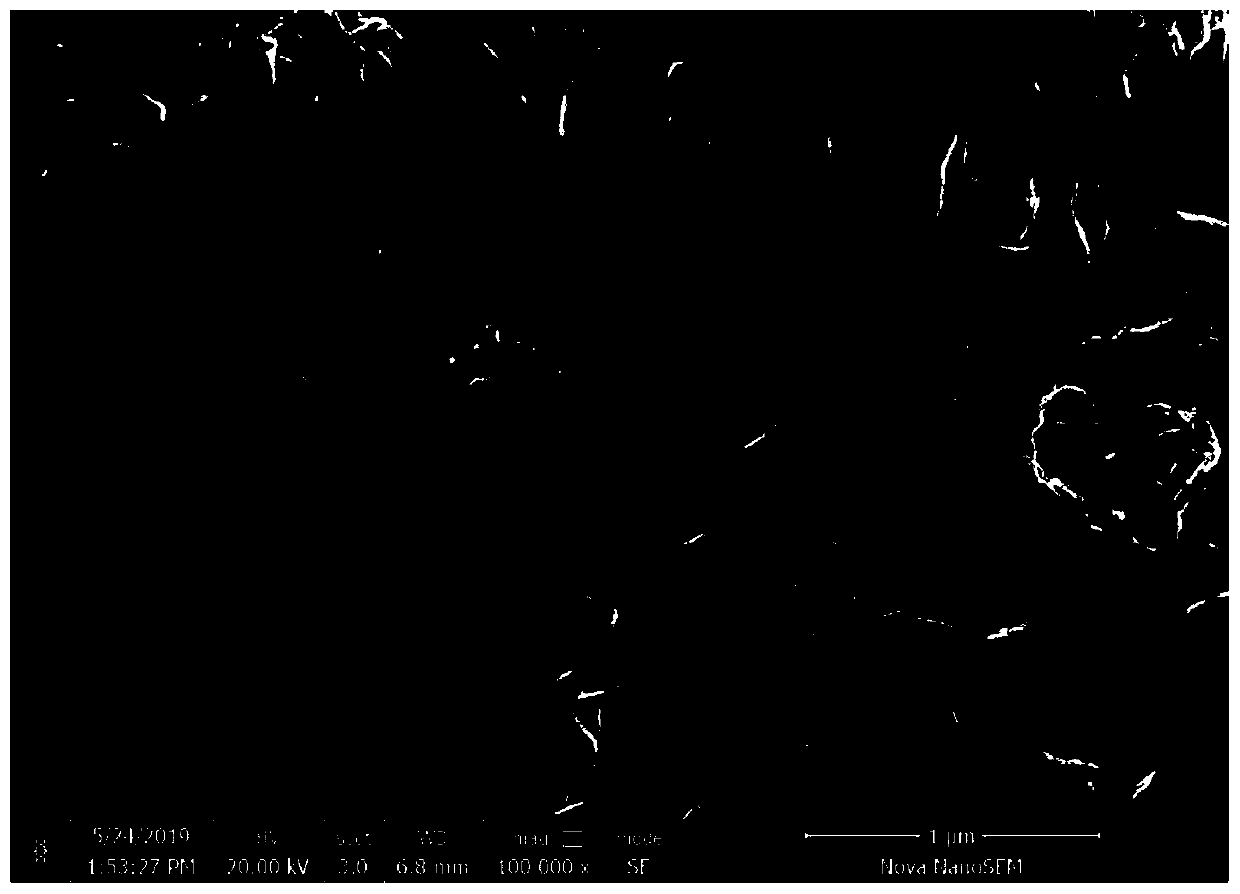
The invention provides a preparation method and application of a nano-catalyst for efficiently treating trimethylamine polluted gas, and belongs to the technical field of odor pollutant treatment andgas phase pollution control. A stainless steel wire is selected as a conductive substrate, a conductive cathode loaded with a Co-MoS2 catalyst is prepared, a catalytic reaction membrane assembly is composed of the conductive cathode and conductive metal anode immersed in 0.5mol / L of a K2SO4 electrolyte solution, the polluted gas in a reactor is removed. According to the preparation method, photoelectro-catalytic technology is combined, under the action of bias voltage, photo-generated charge carriers are driven to different directions, recombination of electrons and holes is effectively inhibited, and the catalyzing efficiency of the catalyst is improved. The preparation method of the nano-catalyst has the beneficial effects that the synthesized Co-MoS2 composite catalyst is evenly dispersed in petal shapes, trimethylamine can be removed in a short time through the photoelectrochemistry synergistic effect, and the purpose of air purifying is achieved.

Description

technical field [0001] The invention belongs to the technical field of malodorous gas treatment, and provides a petal-shaped Co-MoS that efficiently removes trimethylamine malodorous gas in the air 2 Composite materials, coupled with the bias potential generated by metal corrosion, construct a photoelectric coupling catalytic system, which improves the photocatalytic efficiency. The catalyst has a high removal rate of trimethylamine, a stable effect, and is applicable to a wide range of pollutant concentrations. Background technique [0002] As we all know, malodorous pollutants are a kind of special odorous gases, which refer to all gaseous substances that stimulate the olfactory organs, cause people's unpleasantness and damage the living environment. It is a typical nuisance pollution and is also the focus of current complaints. Trimethylamine is a colorless, toxic, flammable simple organic amine gas that produces an unpleasant and pungent ammonia and fishy odor. It is ...

Claims


Application Information

Patent Timeline
Patent Type & Authority Applications(China)
IPC IPC(8): B01J27/051B01J37/10B01J37/34B82Y30/00B82Y40/00B01D53/86B01D53/72
CPCB01J27/0515B01J37/10B01J37/343B82Y30/00B82Y40/00B01D53/8668B01D2258/06B01J35/33B01J35/39
Inventor 柳丽芬闫彩
Owner DALIAN UNIV OF TECH
Learn More