
A photoelectric integrated stretchable flexible nerve electrode and its preparation method

A photoelectric integration and electrode technology, applied in the field of biomedical engineering, can solve problems such as high device integration requirements, weak adhesion, and complex processing technology, and achieve low difficulty in MEMS processing technology, ensure reliability, and improve tensile strength sexual effect

Active Publication Date: 2020-10-30
SHANGHAI JIAO TONG UNIV
View PDF1 Cites 2 Cited by
  • Summary
  • Abstract
  • Description
  • Claims
  • Application Information

AI Technical Summary

Problems solved by technology

However, due to the weak adhesion of polyimide and PDMS itself, it is difficult to ensure that the device does not delaminate during use, and also only has a single EEG recording function, not combined with light stimulation.
[0007] In summary, there is currently no report of a stretchable brain-computer interface flexible electrode that integrates precise light stimulation and cortical electrical signal acquisition. The reasons include complex processing technology and high requirements for device integration, so it is urgent to develop a flexible electrode. It can be implanted for a long time, is highly flexible, can withstand deformation effects such as expansion and contraction, and integrates flexible nerve electrodes with precise light stimulation functions to meet the needs of various brain science and neuroscience research tools.

Method used


Image

  • A photoelectric integrated stretchable flexible nerve electrode and its preparation method
  • A photoelectric integrated stretchable flexible nerve electrode and its preparation method
  • A photoelectric integrated stretchable flexible nerve electrode and its preparation method

Examples


Embodiment Construction

[0069]The present invention will be described in detail below in conjunction with specific embodiments. The following examples will help those skilled in the art to further understand the present invention, but do not limit the present invention in any form. It should be noted that those skilled in the art can make several modifications and improvements without departing from the concept of the present invention. These all belong to the protection scope of the present invention. Parts that are not described in detail in the following embodiments of the present invention can be implemented by using existing technologies.

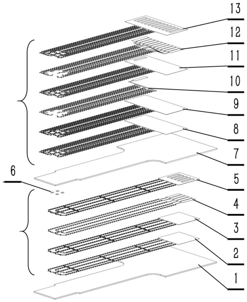
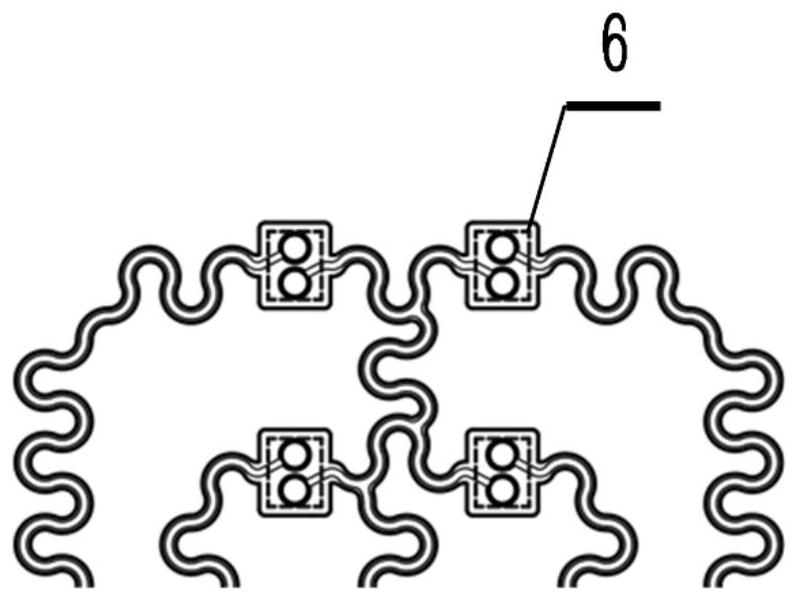
[0070] refer to Figure 1a , 1b , 1c is a schematic structural view of a preferred embodiment of a photoelectrically integrated stretchable flexible nerve electrode, the flexible nerve electrode includes a first layer of elastic substrate 1, a light stimulation electrode, a second layer of elastic substrate 7 and a recording electrode; Both the stimulating...


PUM

PropertyMeasurementUnit
thicknessaaaaaaaaaa
thicknessaaaaaaaaaa
thicknessaaaaaaaaaa

Abstract

The invention provides a photoelectric integrated stretchable flexible neural electrode and a preparation method. The flexible neural electrode comprises a first elastic substrate, a photostimulationelectrode, a second elastic substrate and a recording electrode, and the photostimulation electrode and the recording electrode are both in snakelike curved wire arrangement structures. The lower surface of the photostimulation electrode is provided with a first silicon dioxide layer, and the photostimulation electrode is bonded to the surface of the first elastic substrate by strong chemical bonds generated in condensation reaction of the first silicon dioxide layer and the first elastic substrate. The upper surface of the photostimulation electrode is provided with the second elastic substrate, the lower surface of the recording electrode is provided with a second silicon dioxide layer, and the recording electrode is bonded to the surface of the second elastic substrate through strong chemical bonds generated in condensation reaction of the second silicon dioxide layer and the second elastic substrate, so that the recording electrode and the photostimulation electrode are integratedstructurally. The flexible neutral electrode is available for long-term implantation, high in flexibility and capable of bearing deformation influences of brain tissue expansion and shrinkage and thelike.

Description

technical field [0001] The invention belongs to the nerve microelectrode in the technical field of biomedical engineering, and in particular relates to a photoelectric integrated stretchable flexible nerve electrode and a preparation method thereof. Background technique [0002] With the rapid progress and development of brain-computer interface and neuroscience, an in-depth understanding of brain function and diseases has become one of the frontiers of research around the world. With the help of flexible electronic science and MEMS micro-nano processing capabilities, flexible neural microelectrodes are increasingly used to accurately collect high-density, high-information EEG signals, providing a basis for research on neural circuit functions, diagnosis of brain lesions, and neural decoding. provide new tools. [0003] Since the emergence of optogenetics, which allows people to precisely stimulate or inhibit a specific type of neuron, it has become an indispensable tool fo...

Claims


Application Information

Patent Timeline
Patent Type & Authority Patents(China)
IPC IPC(8): A61B5/0478
CPCA61B5/291
Inventor 刘景全吉博文郭哲俊王隆春
Owner SHANGHAI JIAO TONG UNIV
Learn More