
Co-curing manufacturing die and co-curing manufacturing process method for integral bow capof unmanned aerial vehicle

A manufacturing process and mold manufacturing technology, which is applied in the co-curing manufacturing mold and process field of the overall nose cover of the drone, can solve the problem of no honeycomb sandwich nose cover, the inability to use the overall nose cover, and affecting the dielectric properties of the structure, etc. problem, to achieve the effect of reducing the secondary bonding assembly cycle, solving the limitation of the operating space, and benefiting the dielectric properties

Inactive Publication Date: 2019-10-22
XIAN AISHENG TECH GRP +1
View PDF5 Cites 5 Cited by
  • Summary
  • Abstract
  • Description
  • Claims
  • Application Information

AI Technical Summary

Problems solved by technology

[0003] China Patent Authorization Announcement No. CN 203032934 U, titled carbon fiber composite nose cover parts for aircraft, adopts laminate structure, is suitable for those without wave-transparent performance requirements, and cannot be generally used in the development of integral nose covers
Or use a combined female mold design; because the female mold structure is too deep, the designed combined female mold cannot be operated, and the operating space is insufficient when laying the inner layer, and the secondary bonding affects the dielectric properties of the structure
Moreover, in the prior art, split molding can only guarantee the accuracy of one outer surface. At present, there is no patent report on the integrated design and manufacture of the honeycomb sandwich machine hood.

Method used


Image

  • Co-curing manufacturing die and co-curing manufacturing process method for integral bow capof unmanned aerial vehicle
  • Co-curing manufacturing die and co-curing manufacturing process method for integral bow capof unmanned aerial vehicle
  • Co-curing manufacturing die and co-curing manufacturing process method for integral bow capof unmanned aerial vehicle

Examples


Embodiment Construction

[0035] The embodiments described below by referring to the figures are exemplary and are intended to explain the present invention and should not be construed as limiting the present invention.

[0036] In describing the present invention, it should be understood that the terms "center", "longitudinal", "transverse", "length", "width", "thickness", "upper", "lower", "front", " Orientation indicated by rear, left, right, vertical, horizontal, top, bottom, inside, outside, clockwise, counterclockwise, etc. The positional relationship is based on the orientation or positional relationship shown in the drawings, which is only for the convenience of describing the present invention and simplifying the description, rather than indicating or implying that the referred device or element must have a specific orientation, be constructed and operated in a specific orientation, Therefore, it should not be construed as limiting the invention.

[0037] Now combined with the honeycomb sandw...


PUM


Abstract

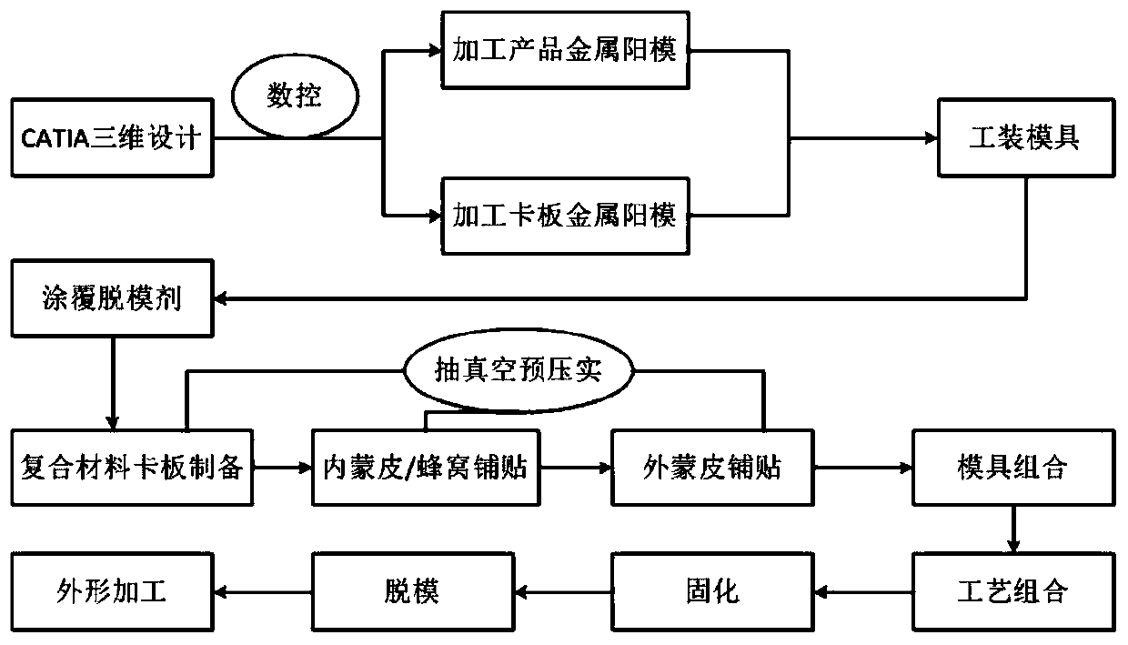
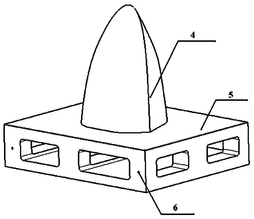
The invention discloses a co-curing manufacturing die and co-curing manufacturing process method for an integral bow cap of an unmanned aerial vehicle, and belongs to the technical field of carbon fiber composite material forming processes in the aviation industry. The co-curing manufacturing die comprises a product metal male die, a product metal male die base, a profile clamping plate metal maledie and a base, wherein the size of the profile structure of the product metal male die is consistent with the size of the inner structure of the bow cap product; the size of the profile structure ofthe profile clamping plate metal male die is consistent with the size of the profile structure of the bow cap product; and the process steps of paving, vacuumizing, curing and demoulding are adoptedto manufacture the integral bow cap of an integrally formed honeycomb sandwich structure. According to the co-curing manufacturing die and the co-curing manufacturing process method, the profile precision and the outer surface quality and precision can be ensured, the processing time is shortened in the whole processing process, the number of the processing procedures is reduced, and the cost is saved.

Description

technical field [0001] The invention belongs to the technical field of carbon fiber composite material forming technology in the aviation industry, and in particular relates to a co-curing manufacturing mold and a process method for the overall hood of an unmanned aerial vehicle. Background technique [0002] Advanced carbon fiber composite materials have the characteristics of high specific strength, specific modulus, and strong designability. Due to the requirements of lightweight design, more and more aircraft are designed with composite materials. Reasonable design can greatly reduce the structural weight, improve the overall performance of the airframe, increase the task load, and extend the battery life. The use of composite materials has become one of the important indicators of the advanced nature of a UAV, generally around 60%-80%, or even a full composite structure, fuselage, wings, tail brace, rudder surface, flat tail, auxiliary wing etc. [0003] China Patent...

Claims


Application Information

Patent Timeline
IPC IPC(8): B29C70/34B29C70/84B29C70/54B29C33/38
CPCB29C33/3835B29C33/3842B29C70/342B29C70/54B29C70/84
Inventor 段国晨王汝敏赵景丽
Owner XIAN AISHENG TECH GRP
Learn More