
Non-contact detection method for heart rate

A non-contact, detection method technology, applied in the measurement of pulse rate/heart rate, character and pattern recognition, diagnostic record/measurement, etc., can solve the problems of rubber allergy, complicated equipment, affecting doctors' judgment, etc., to achieve high accuracy, Easy to detect effects

Inactive Publication Date: 2019-10-22
CHANGSHU GAOSHIDA PHOTOELECTRICITY TECH
View PDF7 Cites 2 Cited by
  • Summary
  • Abstract
  • Description
  • Claims
  • Application Information

AI Technical Summary

Problems solved by technology

[0004] Among them, the disadvantages of using traditional sensors for heart rate detection are: the required equipment is more complicated, the placement of cuffs or electrodes requires professional medical personnel to operate, and the measurement process has strict requirements on the position and posture of the subject, which is not applicable. in daily monitoring
[0005] The disadvantages of heart rate detection based on PPG technology are: contact measurement has limitations, for example, patients with large area burns and scalds cannot perform contact measurement, the delicate skin of newborns is easily damaged by sticky probes, and some people with sensitive skin may Allergy to the adhesive or rubber on the probe, etc.
Secondly, the pressure between the contact probe and the measured part will also affect the accuracy of the measurement results
In addition, some of the testees will change their physiological indicators due to tension after the instrument is placed on their bodies, such as increased heart rate and blood pressure.

Method used


Image

  • Non-contact detection method for heart rate

Examples


Embodiment Construction

[0019] The following will clearly and completely describe the technical solutions in the embodiments of the present invention with reference to the accompanying drawings in the embodiments of the present invention. Obviously, the described embodiments are only some, not all, embodiments of the present invention. Based on the embodiments of the present invention, all other embodiments obtained by persons of ordinary skill in the art without making creative efforts belong to the protection scope of the present invention.

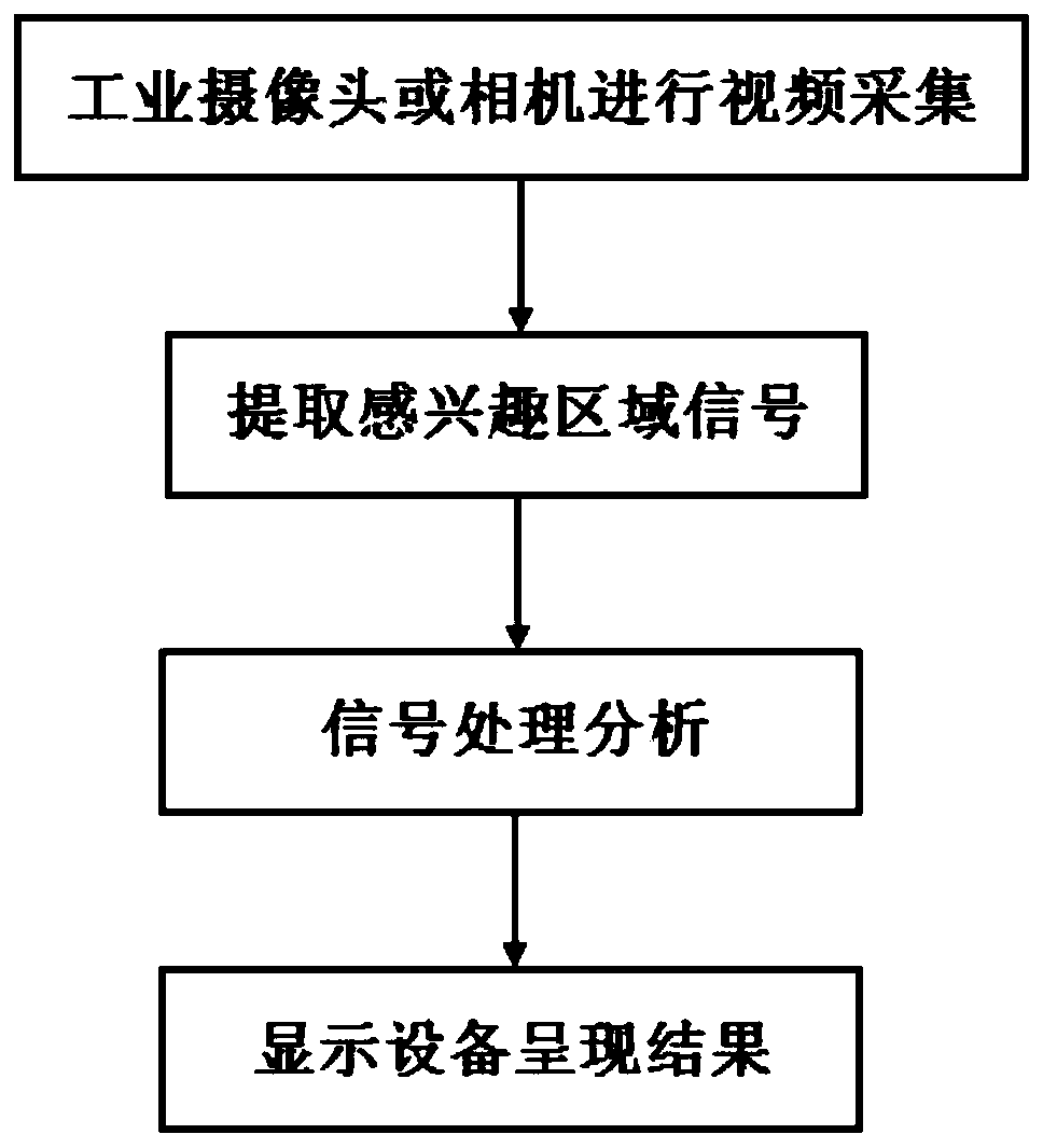
[0020] see figure 1 , an embodiment provided by the present invention: a non-contact heart rate detection method, comprising the following steps:

[0021] Step 1: Choose an industrial camera or camera;

[0022] Step 2: The subject stands at a distance of 1-1.5 meters from the camera or camera, the subject faces the camera or camera, keeps still, and uses the industrial camera or camera to record a video of the subject's face;

[0023] Step 3: Intercept the a...


PUM


Abstract

The invention discloses a non-contact detection method for the heart rate. The method comprises the following steps that a forehead glabellar periphery of an examinee in a video is selected as an interested area, and a blood volume pulse signal is extracted; each frame of image of the shot video is decomposed into different spatial resolutions, the color change is amplified, through an image synthesis technology, a final image is obtained through synthesis, a gray average of each frame of the interested area image of the synthesized final image is acquired through solution, a change waveform of a gray average frame follow-up series is drawn, and a blood volume pulse wave waveform is obtained; the obtained blood volume pulse wave waveform is subjected to noise removal reconstruction throughthe wavelet basis function, and the reconstructed blood volume pulse wave waveform is subjected to FFT transformation to obtain a spectrogram of the waveform, and a frequency, corresponding to the largest energy, in the frequency domain is a frequency of the heart rate. According to the non-contact detection method for the heart rate, non-contact detection of a common industrial camera or a camera is achieved, the measurement result is high in accuracy, detection is conveniently conducted, and the demand for daily heart rate detection can be met.

Description

technical field [0001] The invention relates to the technical field of heart rate detection, in particular to a non-contact heart rate detection method. Background technique [0002] The purpose of the present invention is to provide a non-contact heart rate detection method, which uses an ordinary industrial camera or camera for video acquisition, extracts the signal of the region of interest, and presents the result on the display device after signal processing and analysis. [0003] The technical scheme most similar to the present invention has: 1, utilize traditional sensor to carry out the method for heart rate detection to have arterial pressure method and electrocardiogram (electrocardiogram, ECG) method; Arterial pressure method uses air pump to arterial pressurization, detects pulse by pressure sensor The pressure signal to obtain the heart rate, which is usually used in conjunction with blood pressure measurement; the electrocardiogram is the curve graph of the ele...

Claims


Application Information

Patent Timeline
IPC IPC(8): A61B5/024A61B5/00G06K9/00G06K9/32
CPCA61B5/02416A61B5/7203A61B5/7257G06V40/171G06V10/25G06F2218/04G06F2218/08
Inventor 章冠华高洋叶黎达陆炯
Owner CHANGSHU GAOSHIDA PHOTOELECTRICITY TECH
Learn More