Light emitting panel manufacturing method, light emitting panel and display device

A technology of light-emitting panels and light-emitting devices, which is applied in semiconductor/solid-state device manufacturing, electrical components, electric solid-state devices, etc., and can solve problems such as cumbersome operation process, inconspicuous effect, and poor conductivity

Inactive Publication Date: 2019-10-18
SHENZHEN CHINA STAR OPTOELECTRONICS SEMICON DISPLAY TECH CO LTD
View PDF5 Cites 2 Cited by
  • Summary
  • Abstract
  • Description
  • Claims
  • Application Information

AI Technical Summary

Problems solved by technology

However, in the current contact hole structure, since there is an electron transport layer (Electron Transport Layer, ETL) with poor conductivity between the auxiliary cathode and the surface cathode, it is often necessary to use a high voltage to burn it in. This operation process is cumbersome and the effect is not obvious

Method used


Image

  • Light emitting panel manufacturing method, light emitting panel and display device
  • Light emitting panel manufacturing method, light emitting panel and display device
  • Light emitting panel manufacturing method, light emitting panel and display device

Examples


Embodiment Construction

[0049] The technical solutions in the embodiments of the present application will be clearly and completely described below in conjunction with the drawings in the embodiments of the present application. Apparently, the described embodiments are only some of the embodiments of this application, not all of them. Based on the embodiments in this application, all other embodiments obtained by those skilled in the art without making creative efforts belong to the scope of protection of this application.

[0050] In the prior art, in the direction of large-size OLED screens, the existing marketed products are concentrated in the bottom (Bottom) light-emitting structure, and the cathode uses a thicker alkali metal. However, as users have higher and higher requirements for resolution, OLEDs with a Bottom structure will be limited by the aperture ratio, making it difficult to achieve higher resolution. Therefore, more and more manufacturers are turning their energy to the development...


PUM


Abstract

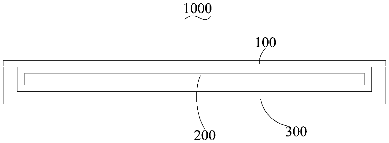
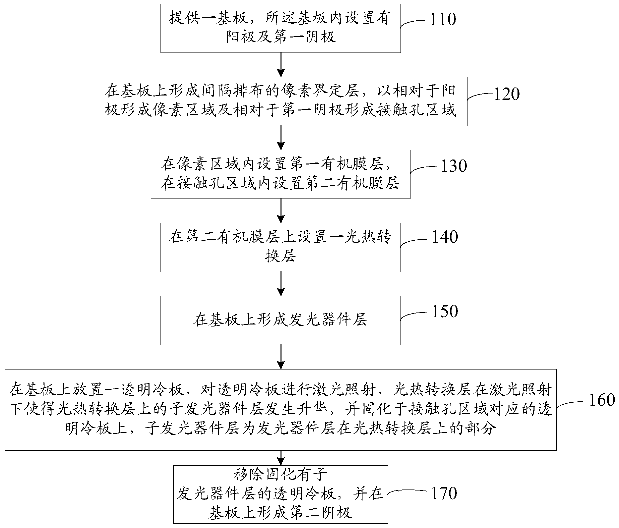
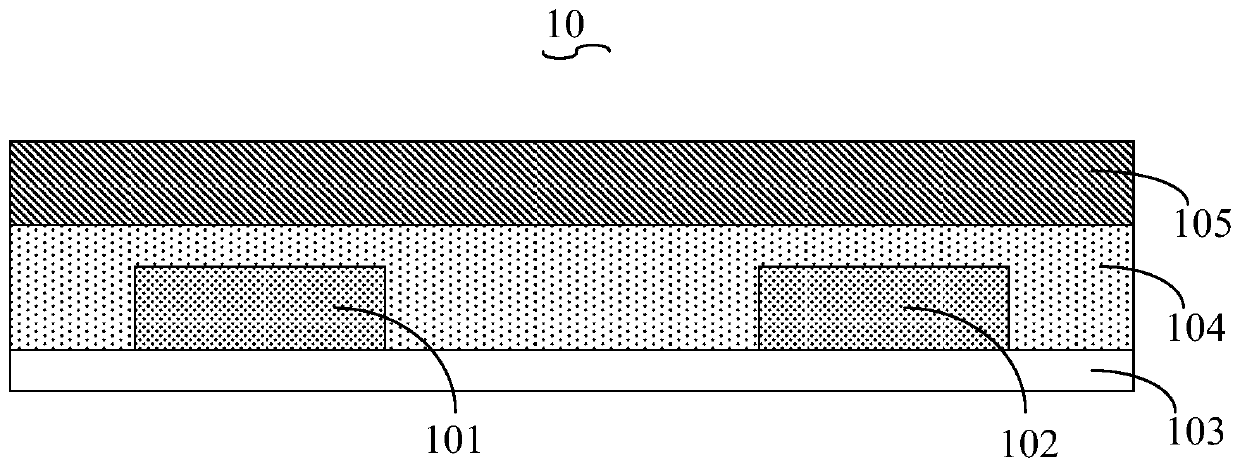
The invention discloses a light emitting panel manufacturing method, a light emitting panel and a display device. The method comprises steps that a substrate is provided, and an anode and a first cathode are disposed in the substrate; spaced-apart pixel defining layers are formed on the substrate to form a pixel region with respect to the anode and a contact hole region with respect to the first cathode; a first organic film layer is disposed in the pixel region, and a second organic film layer is disposed in the contact hole region; a photothermal conversion layer is disposed on the second organic film layer; a light emitting device layer is formed on the substrate; a transparent cold plate is placed on the substrate, the transparent cold plate is subjected to laser irradiation, the photothermal conversion layer under laser irradiation makes a sub light emitting device layer on the photothermal conversion layer sublimate, the sub light emitting device layer is cured on the transparentcold plate corresponding to the contact hole region, and the sub light emitting device layer is a portion of the light emitting device layer on the photothermal conversion layer; the transparent coldplate cured with the sub light emitting device layer is removed, and a second cathode is formed on the substrate.

Description

technical field [0001] The present application relates to the field of display technology, in particular to a method for preparing a light-emitting panel, a light-emitting panel and a display device. Background technique [0002] In recent years, organic light emitting devices (Organic Light Emitting Diode, OLED) have become the most promising new display devices in recent years due to their advantages such as self-luminescence, all-solid-state, and high contrast. In the direction of large-size OLED screens, the existing products on the market are concentrated in the bottom emission structure, and the cathode uses thicker alkali metal. However, as users have higher and higher requirements for resolution, the OLED with the bottom structure will be limited by the aperture ratio, making it difficult to achieve higher resolution. Therefore, more and more manufacturers are turning their energy to the development of top OLEDs, hoping to achieve higher resolution. [0003] Howeve...

Claims


Application Information

Patent Timeline
IPC IPC(8): H01L27/32H01L51/52H01L51/56
CPCH10K59/122H10K50/822H10K50/824H10K71/00
Inventor 潘凌翔吴元均
Owner SHENZHEN CHINA STAR OPTOELECTRONICS SEMICON DISPLAY TECH CO LTD
Why Eureka
Try Eureka