Engine cylinder liner

A technology for engine cylinders and cylinder liners, which is applied in heat treatment equipment, furnaces, quenching devices, etc., can solve problems such as the adverse effects of peripheral rings, high coolant surface temperature, and poor cooling rate, so as to avoid cylinder liner erosion and environmental pollution , Improve the effect of quenching quality

Inactive Publication Date: 2020-10-30
安徽省天鑫内燃机配件有限公司
View PDF0 Cites 0 Cited by
  • Summary
  • Abstract
  • Description
  • Claims
  • Application Information

AI Technical Summary

Problems solved by technology

[0002] After the machining of the cylinder liner is completed, in order to improve the strength of the inner wall of the cylinder liner, the inner wall of the cylinder liner needs to be quenched. There are two main ways of quenching the traditional cylinder liner. One is to spray the heated inner wall of the cylinder liner with coolant. The cooling liquid supply speed is the first in the first way, so the cooling rate is poor, and it is difficult to achieve the ideal quenching effect; the other is to directly submerge the heated cylinder liner into the cooling liquid. The defect of this quenching method is that the cooling liquid is always The surface liquid first contacts with the high-temperature cylinder liner, resulting in a higher surface temperature of the coolant, which also affects the quenching effect; in addition, these two quenching methods will generate a large amount of smoke, which will erode the inner wall of the cylinder liner on the one hand and affect the surface quality of the cylinder liner , on the other hand, it will adversely affect the surrounding ring

Method used


Image

  • Engine cylinder liner
  • Engine cylinder liner
  • Engine cylinder liner

Examples


Embodiment 1

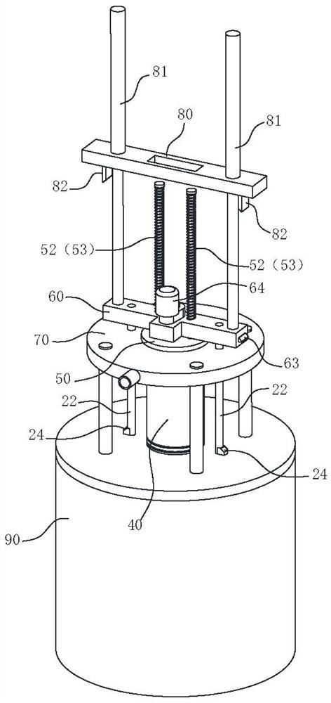
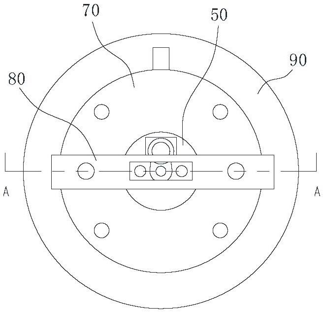
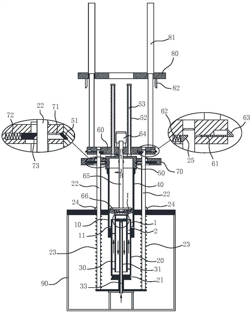
[0029] Such as figure 1 , 2, 3, an engine cylinder liner quenching system, including a first flow channel 1 and a second flow channel 2 arranged in the vertical direction, the first flow channel 1 is annular, and the second flow channel 2 is located in the first flow channel 1 Inside, the lower end of the first flow channel 1 is provided with a liquid outlet, the lower end of the second flow channel 2 is provided with a liquid inlet button, the upper ends of the first flow channel 1 and the second flow channel 2 are connected to each other, and the cylinder liner 40 forms the outer wall or Part of the outer wall, there is a common wall between the first flow channel 1 and the second flow channel 2, and the common wall is reciprocatingly arranged along the vertical direction; it also includes a heating device 66 arranged vertically reciprocatingly along the inner wall of the cylinder liner 40; the present invention During quenching, the common wall is lifted synchronously with...

Embodiment 2

[0039] A kind of engine cylinder liner, adopts following method to make:

[0040] Step 1: casting cylinder liner 40 blanks with a centrifugal casting machine;

[0041] Step 2: Machining the cylinder liner 40 blank to obtain the cylinder liner 40;

[0042] Step 3: Quenching the inner wall of the cylinder liner 40, the quenching operation is performed using the engine cylinder liner quenching system described in Embodiment 1. When quenching, first place the cylinder liner 40 on the barrel-shaped base 10, and then press it tightly with the gland 50 At the top of the cylinder liner 40, insert the heating device 66 into the bottom of the cylinder liner 40; then the heating device 66 starts to heat the inner wall of the cylinder liner 40, and the heating device 66 lifts up while heating, and at the same time, the coolant flows from the second flow channel 2 It is sent to the top of the first flow channel 1, and the common wall between the second flow channel 2 and the first flow ch...


PUM


Abstract

The invention belongs to the technical field of engine cylinder liner processing, and particularly relates to an engine cylinder liner. The engine cylinder liner is produced by the following steps that step 1, a centrifugal casting machine is used to cast a cylinder liner blank; step 2, the cylinder liner blank is machined to obtain a cylinder liner; and step 3, the inner wall of the cylinder liner is quenched. It is ensured that a high temperature area of the cylinder liner is always in contact with cooling liquid in the low temperature state during quenching, thereby improving the quenchingquality; and a cylinder liner quenching system uses a barrel-shaped base and a gland to seal the two ends of the cylinder liner before quenching, the quenching is carried out in a closed environment,flue gas generated by quenching is collected through an exhaust port and sent to an exhaust gas treatment device for harmless treatment, and the cylinder liner burnt and environmental pollution causedby the flue gas retention are effectively avoided.

Description

technical field [0001] The invention belongs to the technical field of engine cylinder liner processing, and in particular relates to an engine cylinder liner. Background technique [0002] After the machining of the cylinder liner is completed, in order to improve the strength of the inner wall of the cylinder liner, the inner wall of the cylinder liner needs to be quenched. There are two main ways of quenching the traditional cylinder liner. One is to spray the heated inner wall of the cylinder liner with coolant. The cooling liquid supply speed is the first in the first way, so the cooling rate is poor, and it is difficult to achieve the ideal quenching effect; the other is to directly submerge the heated cylinder liner into the cooling liquid. The defect of this quenching method is that the cooling liquid is always The surface liquid first contacts with the high-temperature cylinder liner, resulting in a higher surface temperature of the coolant, which also affects the q...

Claims


Application Information

Patent Timeline
Patent Type & Authority Applications(China)
IPC IPC(8): C21D1/62C21D9/00B23P15/00
CPCB23P15/00C21D1/62C21D9/0062C21D9/0068
Inventor 周茜
Owner 安徽省天鑫内燃机配件有限公司
Why Eureka
Try Eureka