
Rapid transfer switch device and system and application

A switching device, fast switching technology, applied in electrical switches, circuit devices, high-voltage/high-current switches, etc., can solve problems such as long switching time, malfunction, and long connection lines

Inactive Publication Date: 2019-10-18
ANHUI HEKAI ELECTRICAL TECH CO LTD
View PDF7 Cites 4 Cited by
  • Summary
  • Abstract
  • Description
  • Claims
  • Application Information

AI Technical Summary

Problems solved by technology

Traditional vacuum circuit breakers generally use a spring operating mechanism, which takes a long time to open and close, and the switching speed is slow, resulting in a power outage for sensitive loads when the switching between the working power vacuum circuit breaker and the standby power vacuum circuit breaker is completed; moreover, the switching of the switch The controller and the actuator circuit breaker (that is, the vacuum circuit breaker for the working power supply and the vacuum circuit breaker for the standby power supply) are set separately. The working power vacuum circuit breaker or backup power vacuum circuit breaker is easily interfered by electromagnetic signals and malfunctions; at the same time, since the working power vacuum circuit breaker and backup power vacuum circuit breaker must be able to extinguish the arc when the current crosses zero, the arc exists for a long time , so that when the power supply is switched, the switch from the working power supply to the standby power supply must be completed after the current of the vacuum circuit breaker of the working power supply crosses zero, or the switch from the standby power supply to the working power supply must be completed after the current of the vacuum circuit breaker of the standby power supply crosses the zero point , the current continues to exist in the half-wave period before the zero crossing point, and the vacuum circuit breaker for the working power supply or the vacuum circuit breaker for the backup power supply cannot complete the breaking, resulting in a long switching time, which cannot meet the switching requirements of sensitive loads

Method used


Image

  • Rapid transfer switch device and system and application
  • Rapid transfer switch device and system and application
  • Rapid transfer switch device and system and application

Examples


Embodiment Construction

[0065] Exemplary embodiments of the present disclosure will be described in more detail below with reference to the accompanying drawings. Although exemplary embodiments of the present disclosure are shown in the drawings, it should be understood that the present disclosure may be embodied in various forms and should not be limited by the embodiments set forth herein. Rather, these embodiments are provided for more thorough understanding of the present disclosure and to fully convey the scope of the present disclosure to those skilled in the art.

[0066] Reference will now be made in detail to the exemplary embodiments, examples of which are illustrated in the accompanying drawings. When the following description refers to the accompanying drawings, the same numerals in different drawings refer to the same or similar elements unless otherwise indicated. The implementations described in the following exemplary examples do not represent all implementations consistent with the ...


PUM


Abstract

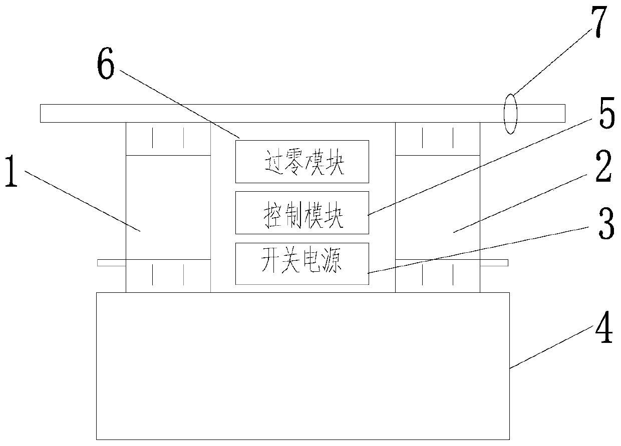
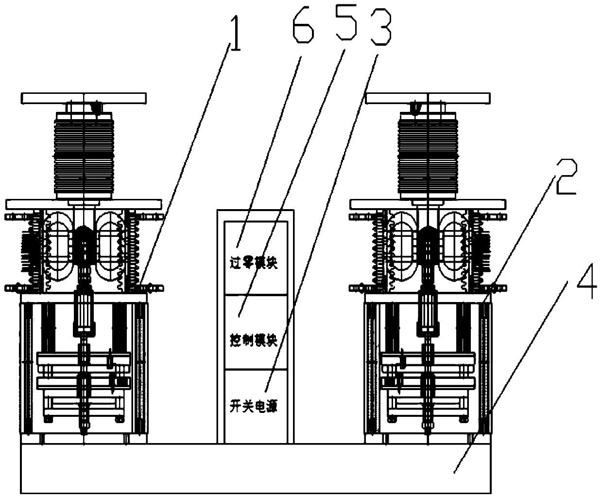
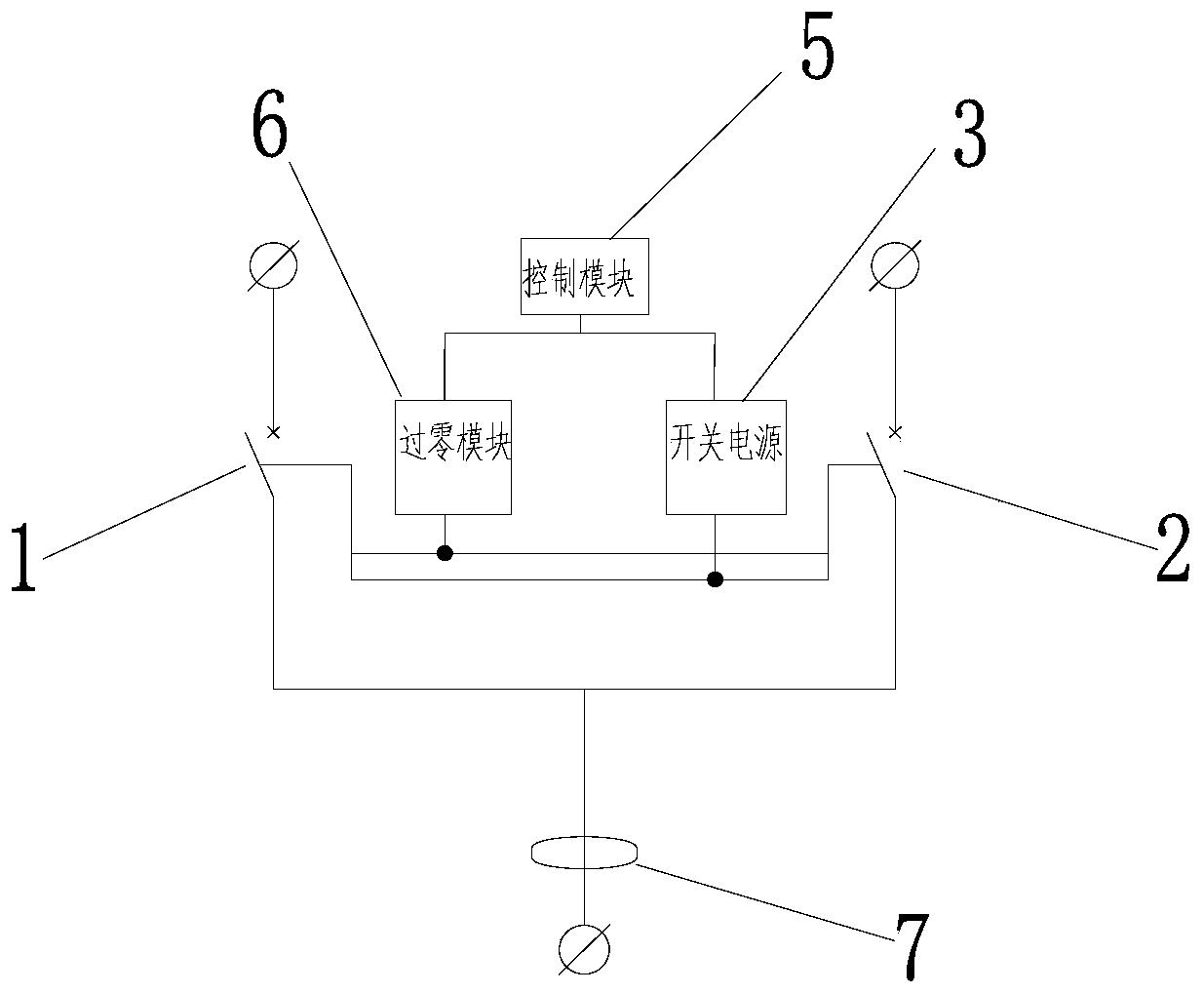
The invention discloses a rapid transfer switch device and system and an application. The rapid transfer switch device comprises a working power supply vacuum circuit breaker, a standby power supply vacuum circuit breaker, a switching power supply, a frame base, a control module, a zero-crossing module and an output current measuring module; the working power supply vacuum circuit breaker, the standby power supply vacuum circuit breaker, the switching power supply, the control module and the zero-crossing module are fixed on the frame base; the control module is connected with the switching power supply, the zero-crossing module and the output current measuring module; the positive output end and the negative output end of the zero-crossing module are connected to moving contacts and static contacts of the working power supply vacuum circuit breaker and the standby power supply vacuum circuit breaker respectively; the output current measuring module is installed on the output bus of the working power supply vacuum circuit breaker and the output bus of the standby power supply vacuum circuit breaker; and the control module is used for sending a switching signal to the switching power supply and the zero-crossing module so as to achieve the two-way switching from the working power supply to the standby power supply, or from the standby power supply to the working power supply. The device disclosed by the invention is high in switching speed and high in reliability.

Description

technical field [0001] The present invention relates to a fast transfer switch device, system and application. Background technique [0002] In the prior art, the transfer switch is generally applied to the switching of the working power supply of the sensitive load. Traditional vacuum circuit breakers generally use a spring operating mechanism, which takes a long time to open and close, and the switching speed is slow, resulting in a power outage for sensitive loads when the switching between the working power vacuum circuit breaker and the standby power vacuum circuit breaker is completed; moreover, the switching of the switch The controller and the actuator circuit breaker (that is, the vacuum circuit breaker for the working power supply and the vacuum circuit breaker for the standby power supply) are set separately. The working power vacuum circuit breaker or backup power vacuum circuit breaker is easily interfered by electromagnetic signals and malfunctions; at the sam...

Claims


Application Information

Patent Timeline
Patent Type & Authority Applications(China)
IPC IPC(8): H01H33/59H01H33/666H02J9/06
CPCH01H33/666H01H33/593H02J9/06
Inventor 李俭华余振
Owner ANHUI HEKAI ELECTRICAL TECH CO LTD
Learn More