Magnetic field measuring method of dynamic excitation magnetic gradiometer

A magnetic gradiometer, magnetic field measurement technology

Inactive Publication Date: 2019-10-18
CHINA UNIV OF GEOSCIENCES (WUHAN)
View PDF6 Cites 0 Cited by
  • Summary
  • Abstract
  • Description
  • Claims
  • Application Information

AI Technical Summary

Problems solved by technology

At present, most magnetometers at home and abroad are single-channel, that is, only one sensor is equipped when working, and can only measure the total field strength of the magnetic field, but the total magnetic field strength is greatly affected by the external magnetic environment, such as the uniformity of the magnetic field, the magnetic field Daily changes and ambient temperature changes, and the sensitivity of single-channel magnetometers in magnetic anomaly detection applications is slightly low, so it is necessary to find magnetic anomalies by measuring magnetic field gradients
[0003] The implementation of a magnetic gradiometer uses two magnetic sensors for magnetic field gradient measurements, thus requiring a magnetic gradiometer excitation-measurement system for simultaneous excitation and simultaneous measurement of the signal, which cannot be met with current systems

Method used


Image

  • Magnetic field measuring method of dynamic excitation magnetic gradiometer
  • Magnetic field measuring method of dynamic excitation magnetic gradiometer
  • Magnetic field measuring method of dynamic excitation magnetic gradiometer

Examples


Embodiment Construction

[0034] In order to have a clearer understanding of the technical features, purposes and effects of the present invention, the specific implementation manners of the present invention will now be described in detail with reference to the accompanying drawings.

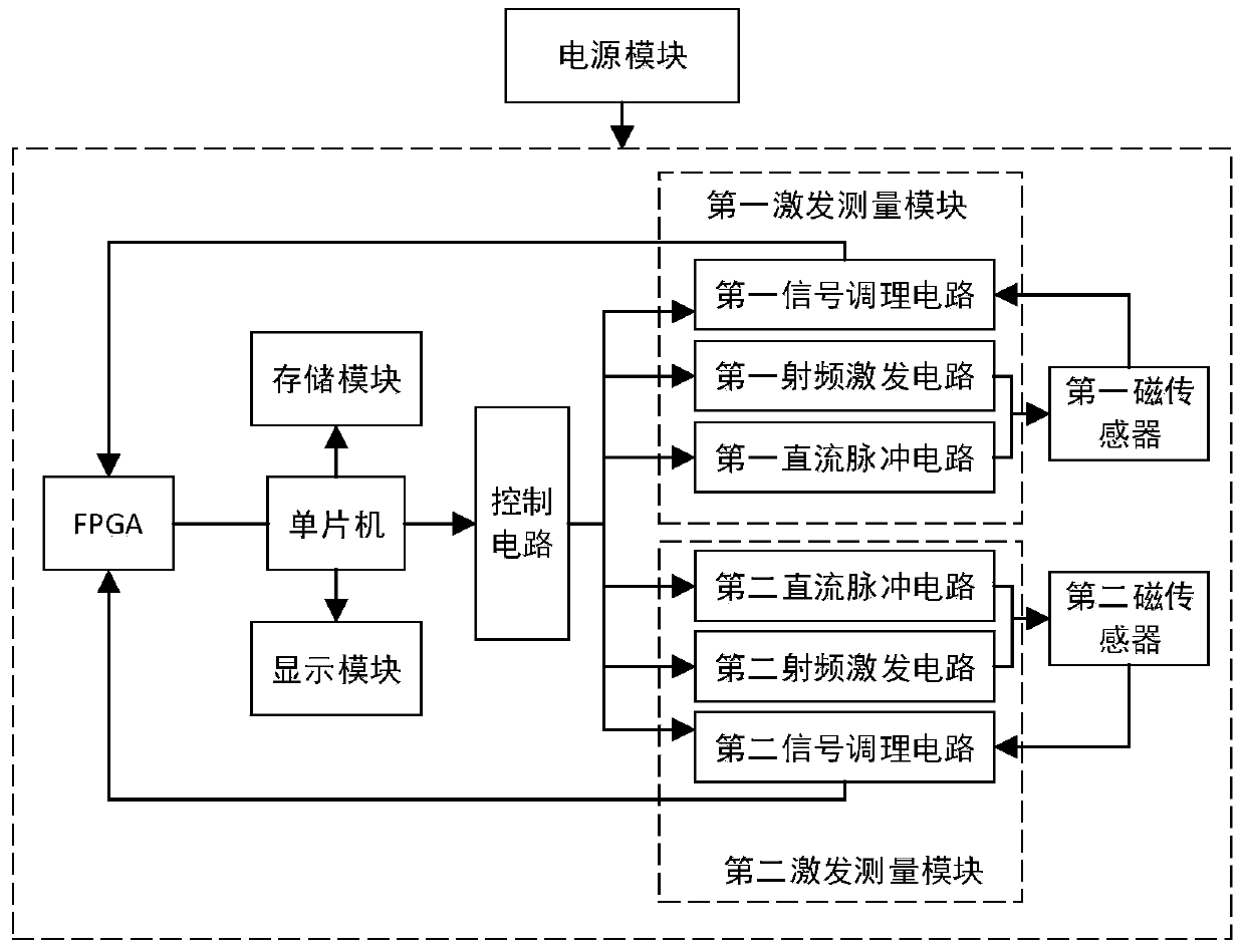
[0035] Embodiments of the present invention provide a magnetic field measurement method of a dynamically excited magnetic gradiometer, which is applied to such as figure 2 In the magnetic field measurement system of a kind of dynamic excitation magnetic gradiometer shown; The magnetic field measurement system of described a kind of dynamic excitation magnetic gradiometer comprises: the first excitation measurement module, the second excitation measurement module, control circuit, FPGA, single-chip microcomputer and magnetic sensor;

[0036] The first excitation measurement module includes: a first DC pulse circuit, a first radio frequency excitation circuit and a first signal conditioning circuit; the second excitation...


PUM


Abstract

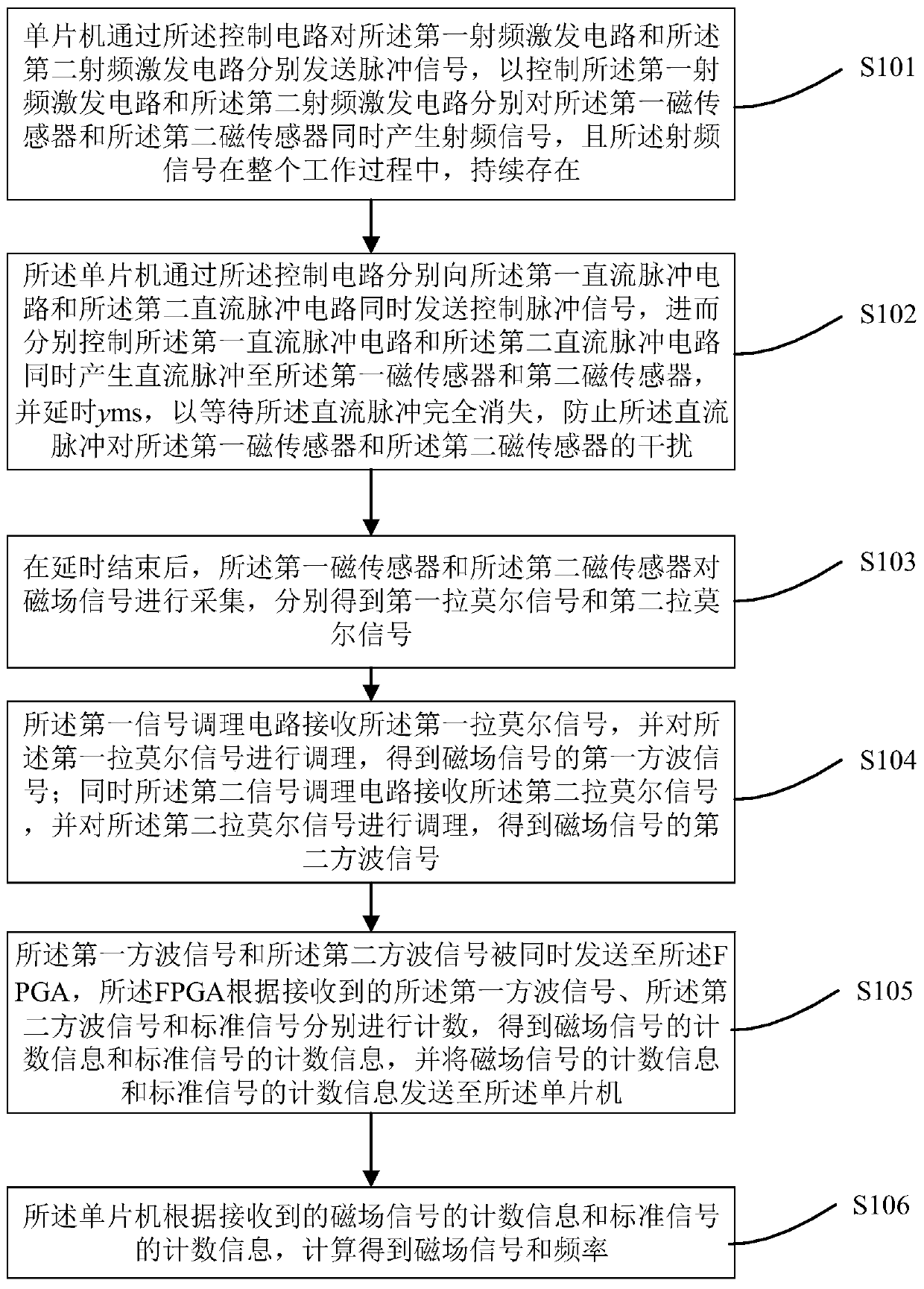
The invention provides a magnetic field measuring method of a dynamic excitation magnetic gradiometer. The magnetic field measuring method comprises the following steps that firstly, double-path direct-current pulse generation, radio frequency excitation and signal conditioning time sequence control are carried out by a single-chip microcomputer through a control circuit, and the control circuit synchronously controls the time-sharing work of a two-path radio-frequency excitation circuit and a two-way signal conditioning circuit according to the single-chip microcomputer time sequence signals;then, the single-chip microcomputer is in communication with an FPGA to convert the frequency measurement information into magnetic field data to calculate the magnetic field gradient; and next, themagnetic field data are stored in a storage module and are displayed through a display module. The technical scheme provided by the invention has the beneficial effects that the same control circuit is used for synchronously controlling the two-path radio-frequency excitation, direct-current pulse and signal conditioning circuits, so that the synchronism of the generation and conditioning of the two-way lamoire signals is guaranteed; and the FPGA is used for synchronously counting the double-path square wave signals and the standard signals, so that synchronous measurement of the frequency information of the two-way lamoire signals is guaranteed.

Description

technical field [0001] The invention relates to the field of magnetic field measurement, in particular to a magnetic field measurement method for dynamically exciting a magnetic gradiometer. Background technique [0002] Dynamic polarization magnetometer is a kind of weak magnetic measuring instrument based on NMR-DNP effect. It has the characteristics of high precision, high sensitivity, low power consumption and continuous measurement. It is widely used in geophysics, aeromagnetic survey and satellite survey. Magnetic, military and various engineering fields. At present, most magnetometers at home and abroad are single-channel, that is, only one sensor is equipped when working, and can only measure the total field strength of the magnetic field, but the total magnetic field strength is greatly affected by the external magnetic environment, such as the uniformity of the magnetic field, the magnetic field Daily changes and ambient temperature changes, and the sensitivity of...

Claims


Application Information

Patent Timeline
IPC IPC(8): G01R33/24G01V3/14G01V3/40
CPCG01R33/24G01V3/14G01V3/40
Inventor 董浩斌王冠中葛健罗望刘欢
Owner CHINA UNIV OF GEOSCIENCES (WUHAN)
Why Eureka
Try Eureka