
A non-weft continuous processing production line

A production line and non-weft fabric technology, applied in the textile field, can solve problems such as low efficiency and unsmooth tearing of the film, and achieve the effect of ensuring accuracy and improving quality

Active Publication Date: 2019-04-23
SUZHOU GANNZ ELECTRONICS TECH CO LTD
View PDF9 Cites 0 Cited by
  • Summary
  • Abstract
  • Description
  • Claims
  • Application Information

AI Technical Summary

Problems solved by technology

[0003] The purpose of the present invention is to address the deficiencies of the prior art, by setting the roller for separating the cloth and the film to be shaken up and down and setting the glue filling part for the cloth to be repaired after the cloth film is separated, thereby overcoming the tearing. The film is not smooth, the efficiency is low, and the glue defect in the cloth after tearing the film affects the quality of the subsequent production of non-woven fabrics.

Method used


Image

  • A non-weft continuous processing production line
  • A non-weft continuous processing production line
  • A non-weft continuous processing production line

Examples


Embodiment 1

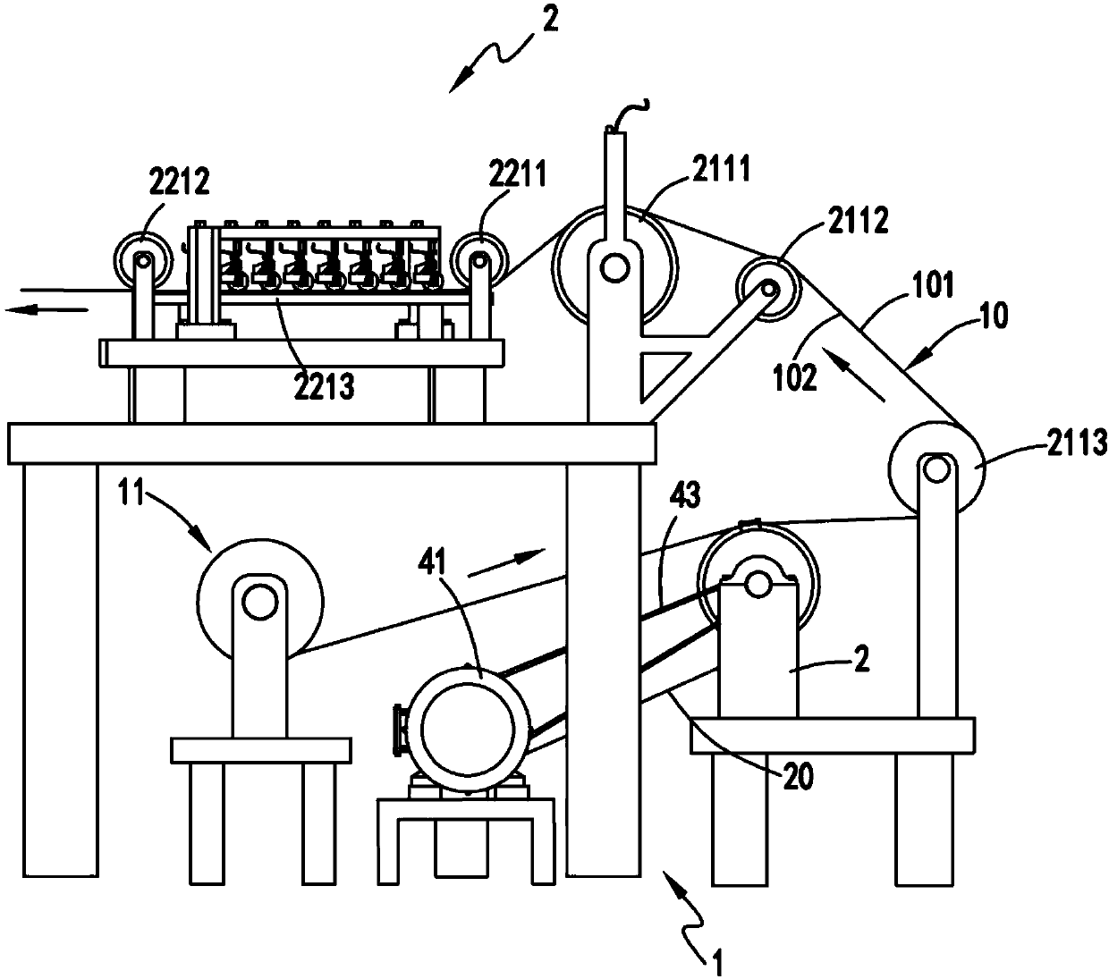
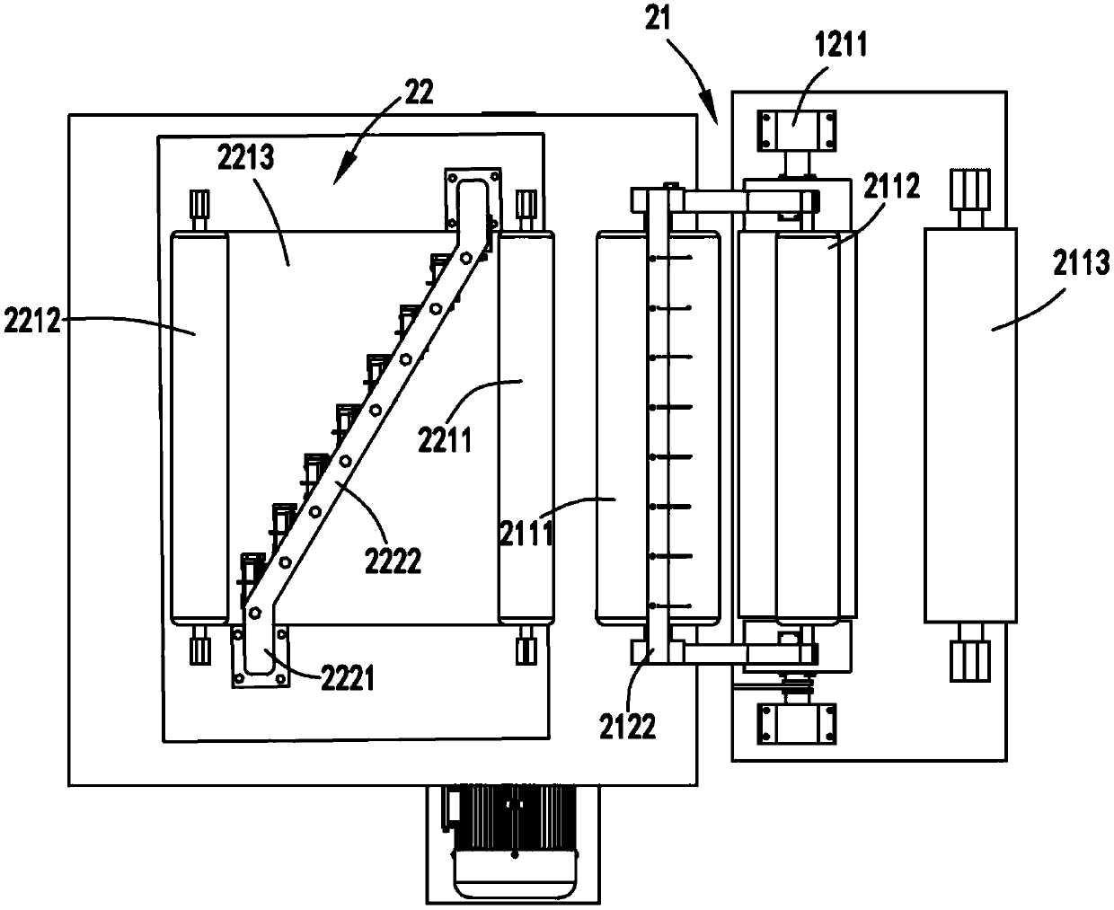
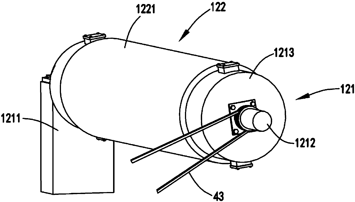
[0052] figure 1 It is a schematic diagram of the front view of the non-weft continuous processing production line, figure 2 It is a top view schematic diagram of the continuous processing line without weft fabric, image 3 Schematic diagram of the structure of the jitter separation mechanism, Figure 4 It is a schematic diagram of the disassembly of the shaking separation mechanism, Figure 5 is a cross-sectional schematic diagram of the vibration separation mechanism, Figure 6 It is a schematic diagram of the structure of the rubber rolling unit, Figure 7 Schematic diagram of the structure when the rubber rolling unit is working, Figure 8 It is a schematic diagram of the structure of the rubber rolling unit in the non-working state, Figure 9 It is a schematic diagram of the structure when the glue outlet hole and the glue guide hole are aligned and connected, Figure 10 It is a schematic diagram of the structure when the glue outlet hole and the glue guide hole are s...

Embodiment 2

[0075] Such as figure 1 , figure 2 , image 3 , Figure 4 , Figure 5 , Figure 6 , Figure 7 , Figure 8 , Figure 9 , Figure 10 , Figure 11 and Figure 12 As shown, the components that are the same as or corresponding to those in the first embodiment are marked with the corresponding reference numerals in the first embodiment. For the sake of simplicity, only the differences from the first embodiment will be described below. The difference between the second embodiment and the first embodiment is that: one side of the control board 322 is provided with a guide plate 35 for guiding the glue flowing out of the glue box 321 to the glue roller 332; It is also provided with a baffle plate 36 for the end to be attached to the surface of the gluing roller 332 in the non-replenishment state.

[0076] The setting of the guide plate 35 enables the glue flowing out of the glue material box 321 to be directed to the surface of the glue roller 332 in time to ensure a good e...


PUM


Abstract

The invention relates to a continuous processing production line of weft-free cloth. The continuous processing production line comprises a film tear part, wherein the film tear part is used for separating cloth from an isolating film of cloth with the film, and a glue filling part for filling a glue-absent region on the separated cloth with glue, wherein the glue filling part comprises a detection mechanism for detecting the glue-absent region on the cloth and a glue filling mechanism which is arranged at the rear end of the detection mechanism and is used for filling the glue-absent region detected by the detection mechanism with the glue under the control of the detection mechanism. The continuous processing production line solves the problems of unsmooth film tearing and low film tearing efficiency and the problem that the quality of subsequently produced weft-free cloth is affected due to absence of the glue on the cloth after the film is torn off.

Description

technical field [0001] The invention relates to the technical field of textiles, in particular to a continuous processing production line without weft fabric. Background technique [0002] The strength of the unidirectional fabric is concentrated in a certain direction, and multiple unidirectional fabrics are cross-stacked at a certain angle to produce a weft-free fabric; in the production process of the unidirectional fabric, it is necessary to paste the produced unidirectional fabric with a film to prevent The one-way cloth is stained with dust and debris, and when it is made into a weft-free cloth, the film needs to be torn off from the one-way cloth. The existing film tearing method is generally manual, and the film tearing process is caused by the difference in viscosity. The tear film is not smooth and the film is easily torn. In addition, there may be glue defects on the cloth after tearing the film. The existing technology does not have the function of repairing the ...

Claims


Application Information

Patent Timeline
Patent Type & Authority Patents(China)
IPC IPC(8): B65H16/06B32B38/10B05C5/00B05C11/10
CPCB05C5/00B05C11/10B32B38/10B65H16/06
Inventor 李重重李开奇李孟鹏
Owner SUZHOU GANNZ ELECTRONICS TECH CO LTD
Learn More