
Automatic film tearing mechanism of manipulator

A manipulator and automatic technology, applied in the directions of layered products, lamination auxiliary operations, lamination, etc., can solve the problems of difference in size, unfavorable processing, low work efficiency, etc., and achieve a simple, practical and precise film-tipping mechanism. Angle, cost saving effect

Pending Publication Date: 2018-08-24
SHENZHEN NUOFENG OPTOELECTRONICS EQUIP
View PDF0 Cites 5 Cited by
  • Summary
  • Abstract
  • Description
  • Claims
  • Application Information

AI Technical Summary

Problems solved by technology

[0002] In production and manufacturing, before processing, many products have a protective film attached to the surface. During processing, the protective film needs to be removed. Usually, two modes of manual tearing and mechanical tearing are used. However, when the two methods are used There are certain disadvantages. First of all, the manual tearing of the film first lifts up a corner of the protective film, and then tears the protective film away from the workpiece. Manual tearing of the film consumes more manpower, and the work efficiency is low, and the manual operation is easy to stain the surface of the product. Conducive to subsequent processing, the mechanical tear film uses easy-to-tear film, high cost, low efficiency, complex mechanism, and because the product has different shapes and sizes, the machine cannot clamp the film corner well, and manual assistance is required

Method used


Image

  • Automatic film tearing mechanism of manipulator
  • Automatic film tearing mechanism of manipulator
  • Automatic film tearing mechanism of manipulator

Examples


Embodiment Construction

[0030] The following will clearly and completely describe the technical solutions in the embodiments of the present invention with reference to the accompanying drawings in the embodiments of the present invention. Obviously, the described embodiments are only some, not all, embodiments of the present invention. Based on the embodiments of the present invention, all other embodiments obtained by persons of ordinary skill in the art without making creative efforts belong to the protection scope of the present invention.

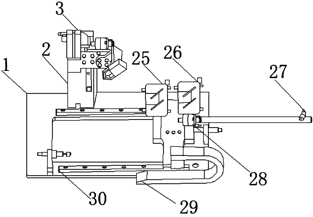
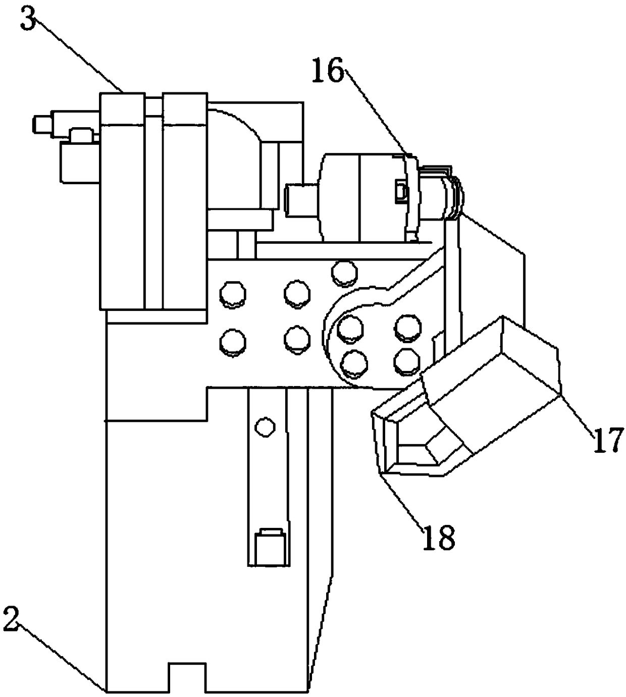
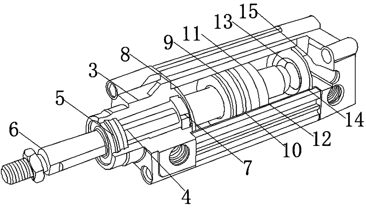
[0031] see Figure 1-5, a manipulator automatic film tearing mechanism, including a base 1, a mechanical column 2 is fixedly installed on the outer surface of the upper end of the base 1, and a film-losing lifting cylinder 3 is fixedly installed on the outer surface of the upper end of the mechanical column 2, The inner center of the film-losing lifting cylinder 3 is fixedly equipped with a bearing 4, the front end of the bearing 4 is fixedly equipped with a p...


PUM


Abstract

The invention discloses an automatic film tearing mechanism of a manipulator. The automatic film tearing mechanism of the manipulator comprises a base, wherein a mechanical column is fixedly mounted on the outer surface of one side of the upper end of the base; a film throwing lifting cylinder is fixedly mounted on the outer surface of the upper end of the mechanical column; a bearing is fixedly mounted in the center of the inside of the film throwing lifting cylinder; a plug rod sealing piece is fixedly mounted at the front end of the bearing; a plug rod is movably mounted in the center of the inner surface of the plug rod sealing piece; a buffer sealing ring is fixedly mounted on the outer surface of one side of the bearing; an end cap sealing ring is fixedly mounted on the outer surfaceof one side of the buffer sealing ring; a piston sealing piece is fixedly mounted on one side of the end cap sealing ring; a piston is fixedly mounted on one side of the piston sealing piece; a magnet is fixedly mounted on the outer surface of one side of the piston; and a wear-resistant ring is fixedly mounted on the outer surface of one side of the magnet. The film tearing mechanism is simple and practical, and is rapid and convenient, carrying films which are torn off are automatically collected in a waste box, a clamping end carries a film corner to finish film tearing, easily torn stickers are not required, and thus, costs are saved.

Description

technical field [0001] The invention relates to the field of online automation, in particular to an automatic film tearing mechanism with a manipulator. Background technique [0002] In production and manufacturing, before processing, many products have a protective film attached to the surface. During processing, the protective film needs to be removed. Usually, two modes of manual tearing and mechanical tearing are used. However, when the two methods are used There are certain disadvantages. First of all, the manual tearing of the film first lifts up a corner of the protective film, and then tears the protective film away from the workpiece. Manual tearing of the film consumes more manpower, and the work efficiency is low, and the manual operation is easy to stain the surface of the product. Conducive to subsequent processing, the mechanical tear film uses easy-to-tear film, which has high cost, low efficiency, complex mechanism, and because the product has different shape...

Claims


Application Information

Patent Timeline
IPC IPC(8): B32B38/10
CPCB32B38/10
Inventor 张德邓永波胡孙华
Owner SHENZHEN NUOFENG OPTOELECTRONICS EQUIP
Learn More